19
Fig.4.5.2: Additional memory size -2
(Unit: MB)
*1:
305 mm x 2,540 mm (12.0 x 100 in.)
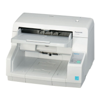
4.6. Installing DIMM Modules
Mode Size dpi
100 200 300 400 500 600
Binary + 8 bit
Gray
*1
SC's Max
128128XXXX
Double Letter 0 128 128 128 128 128
Legal 0 128 128 128 128 128
Letter 0 0 128 128 128 128
A3 0 128 128 128 128 128
A4 0 0 128 128 128 128
A5 0 0 0 128 128 128
A6 0 0 0 0 128 128
B4 0 0 128 128 128 128
B5 0 0 128 128 128 128
B6 0 0 0 128 128 128
Binary +
24 bit Color
*1
SC's Max
256512XXXX
Double Letter 128 128 256 256 512 X
Legal 128 128 128 256 256 256
Letter 128 128 128 256 256 256
A3 128 128 256 256 512 X
A4 128 128 128 256 256 256
A5 0 128 128 128 256 256
A6 0 128 128 128 128 128
B4 128 128 128 256 256 512
B5 0 128 128 128 256 256
B6 0 128 128 128 128 256
1. Remove the Cover Plate. (See 8.2.1.)
2. Insert the DIMM Module into the memory slot (CN0017) on the
CONTROL Board in the direction of the arrow (1), and then
push the module down in the direction of the arrow (2) until
the notches of the module on both sides lock into place.
3. Insert another DIMM Module similarly into the other memory
slot (CN0018) on the CONTROL Board.