Mechanical Instructions
EN 13LC7.1E LA 4.
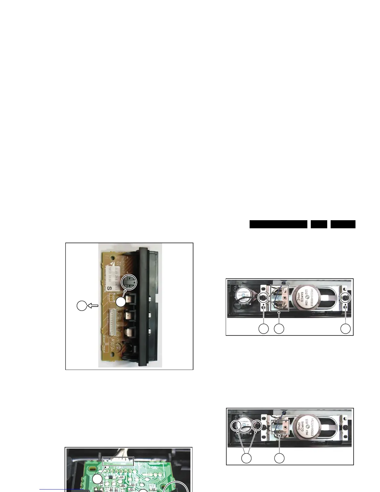
4.3.9 LCD Panel
1. Remove the rear cover, as described earlier.
2. Refer to fig. "LCD panel" below.
3. Unplug the connectors on the Main Supply Panel [a] and
the LED & IR board [c].
4. Unplug the outer connectors [d] from the mid-range
loudspeakers.
5. Do NOT forget to unplug the LVDS connector [e] from the
SSB. Important: Be careful, as this is a very fragile
connector!
6. Remove T10 parker screw [b] that holds the Side I/O
module bracket.
7. Remove T10 parker screws [f] of the central sub-frame.
8. Remove LCD panel fixation screws [g] and lift the complete
central sub-frame from the set (incl. the PSU, SSB, and
Side I/O boards and wiring).
9. Lift the LCD panel [7] from the front cabinet.
Figure 4-17 LCD panel (26" and 32" models)
Figure 4-18 LCD panel (37" and 42" models)
d
d
a
e
G_16860_067.eps
310107
c (1x)
g (2x)
f (3x)
f (2x)
f (1x)
g (2x)
b
d
d
a
e
H_1616940_013.eps
310707
c (1x)
g (2x)
f (3x)
f (1x)
g (2x)
b