EN 22 4. LX9000R Dismantling Instructions
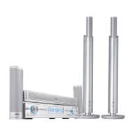
Dismantling the
DVD Basic Engine
• Dismantle Top Cover and Air guide plate as described before.
• Loosen 4 screws as shown in picture 40.
• Plug off cables and fetch the module out.
picture 40
Dismantling the
DVIO Board
• Dismantle Top Cover and Air guide plate as described before.
• Loosen 2 screws as shown in picture 41.
• Disconnect DVIO Board from Digital Board (board to board
connector).
• Take extension board 3104 128 07770 and re-connect DVIO Board
with Digital Board. If necessary, disconnect cable (8006) to Analog
Board.
The DVIO Board is now in a proper service position → see picture 42.
picture 41
DVIO Board
Digital Board
DVIO extension board
3104 128 07770
picture 42
Dismantling the
Digital Board
• Dismantle Top Cover and Air guide plate as described before.
• If necessary, remove DVIO Board first. See description before.
• Loosen 4 screws to dismantle Digital Board.
• To get access to the bottom side, the board can be put to a
service position as shown in picture 43.
Digital Board
DVIO BoarVIO Board
Basic Engine
picture 43
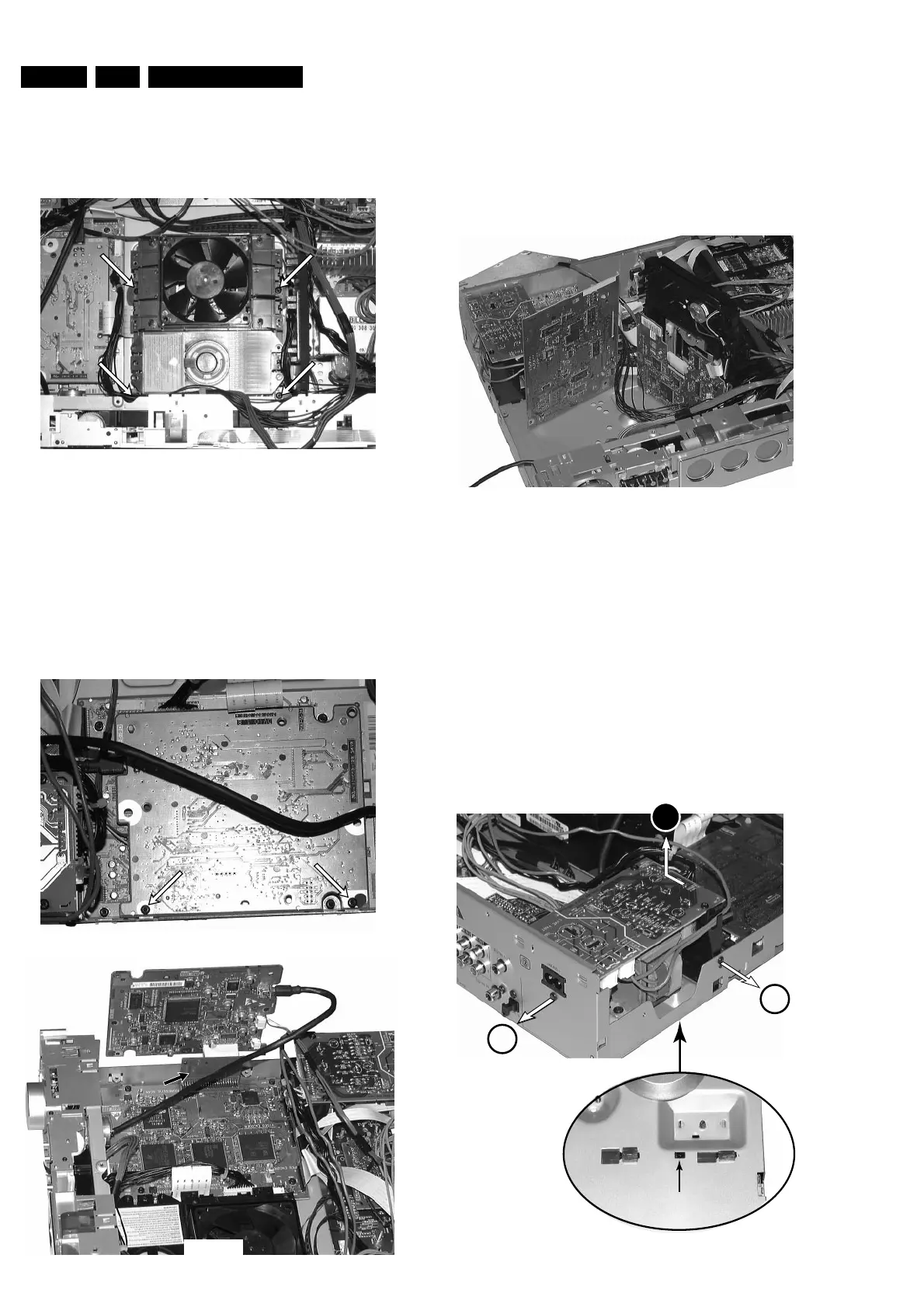
Dismantling the
A/V Board
• Dismantle Top Cover and Air guide plate as described before.
• Dismantle Power primary Board as shown in picture 44.
• Dismantle Standby-transformer and put it together with the Power
primary Board next to the set.
• Loosen 7 screws from rear cabinet as shown inpicture 45.
• Release catches on both sides of the rear cabinet and move it
backwards as far as cable lengts allow → picture 46 shows the
left side catch.
• Loosen 3 screws as shown in picture 47.
• Plug off cables to Auxiliary Board.
• Turn A/V Board to service position as shown in picture 48.
push to release catch
and move left
1
1
2
 Loading...