3-2
SERVICE POSITIONS
Service position A
Service position B
Note: In some service positions the components or copper patterns of one board may risk touching its neighbouring pc
boards or metallic parts. To prevent such short-circuit use a piece of hard paper or other insulating material between them.
3-2
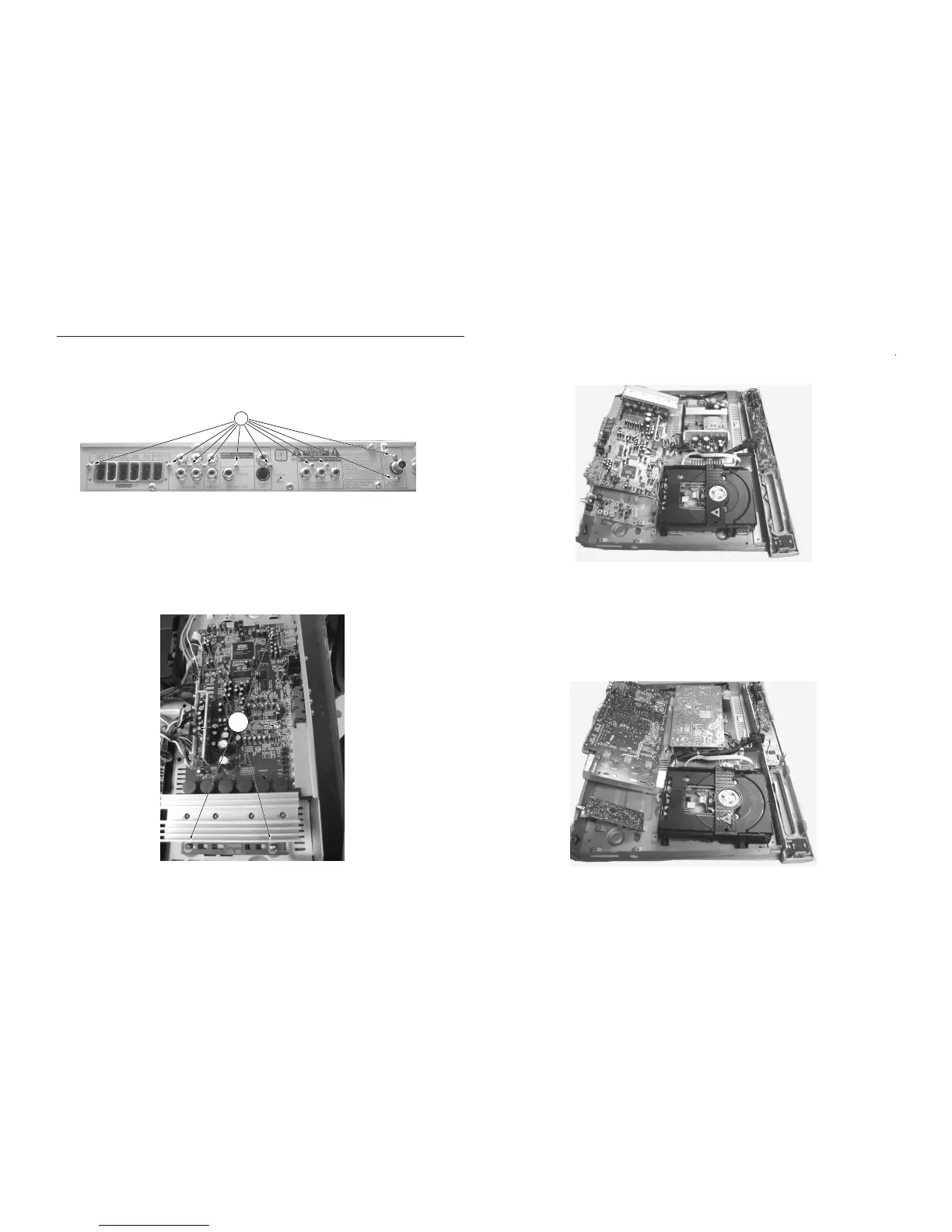
Dismantling of the Tuner PCB
1) Loosen 10 screw " C " at the back panel as shown in figure
7.
2) Loosen 6 screw " D " on the top of main board as shown in
figure 8.
Figure 7
Figure 8
C
D