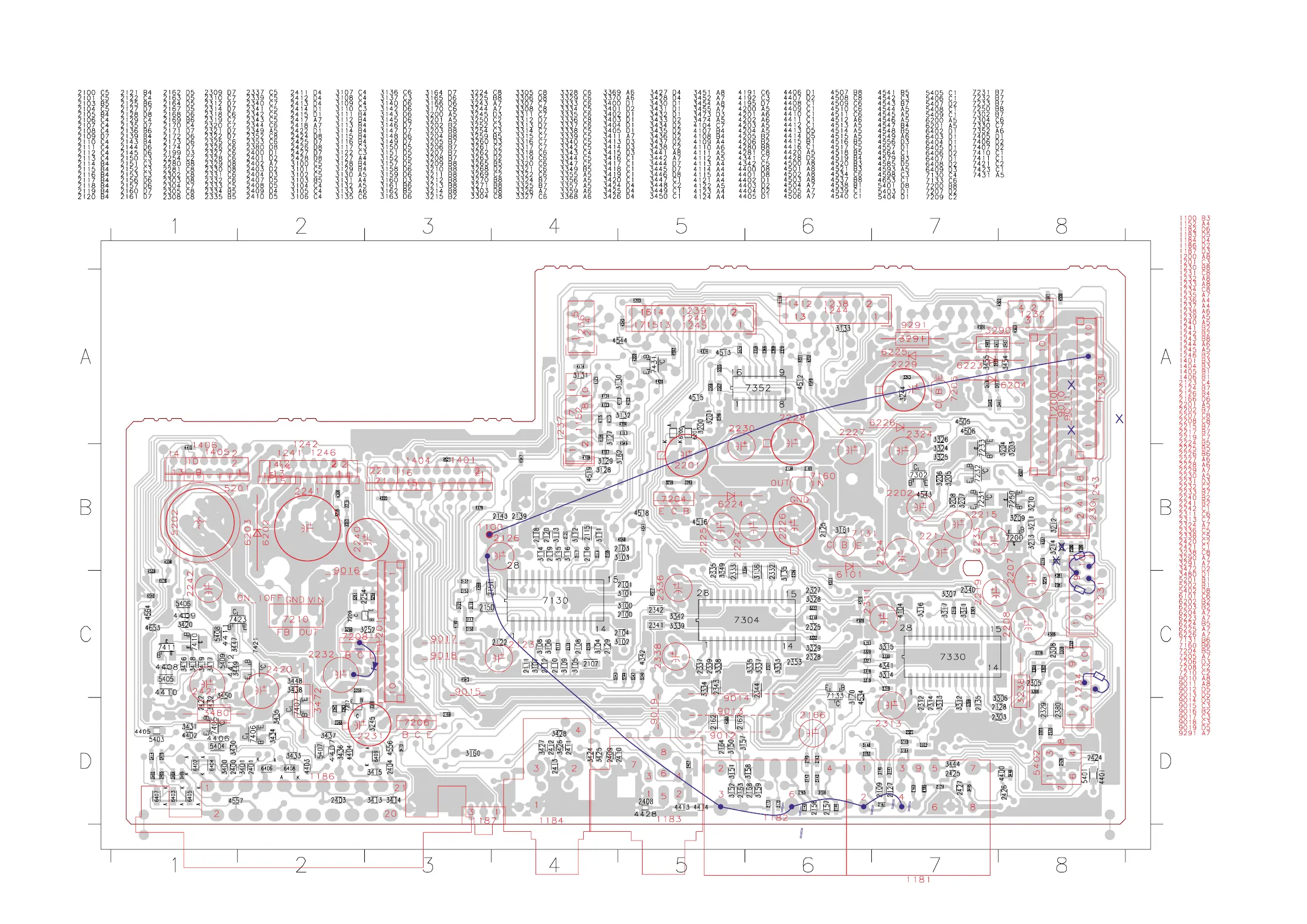
CHIP & COMPONENT LAYOUTS - CHIP SIDE VIEW
9-2
9-2
cut copper pattern at 5 locations
7205
added
3302
added
3271
3270
3270 and 3271
new location
delete 9011
W1
W2
W3
W4
W5
This assembly drawing shows a summary of all possible versions. For components used in a specific version see schematic diagram and respective parts list
Rework at production start-up (provided in blue)
1. Jumper 9011 deleted.
2. Copper pattern cut at 6 places indicated by blue // lines and wires W1 to W5 added.
3. Res 3270 and R3271 shifted to conn 1231 pin 10 and 8 to ground, the original
mounting location deleted.
4. Items 2280, 2281, 4280 and 4281 all mounted with 470nF (12NC: 3198 017 44740)
5. Res 3302 22k (12NC: 3198 021 32230) added.
6. Diode 7205 SS14 (12NC: 9322 128 70685) added after transistor 7208 collector.
(copper pattern at collector is cut as indicated by blue // lines)
7. Transistor 7204 BD438 is mounted with a heatsink. For service it can be replaced
by BD242 (12NC: ....) without need for heatsink but be careful with the pins
configuration.