EasyManua.ls Logo

Philips N 4450 User Manual

Philips N 4450
24 pages
To Next Page IconTo Next Page
Page #1 background imageLoading...
Page #1 background image
.INHALTSVERZEICHNIS
Einführung
Spezifikation
Ein- und Ausgänge
Anschlüsse und Bedienungsorgane
Umschalten auf eine andere Netzspannung
und/oder Netzfrequenz
Funktionelle Einheiten des Verstärkerteils
Beschreibung des Steuerteils
Kurzschlusssicherung in der Endstufe
Funktionelle Einheiten des Steuerteils
Hall-Motor
CS31885
CS31886
CS31887
CS31888
CS31890
CS31708-CS31716
CS31891
CS31892
CS31893-CS31894
CS31895
EINFÜHRUNG
Gerät N4450 ist ein
Stereo-Spulen-Tonbandgerät,
das sich
r Horizontal- und Vertikalbetrieb eignet.
Spulen mit einem Durchmesser bis 26,5 cm
(lOi")
können
r dieses Gerät benutzt werden. Das Band kann sowohl von
links nach rechts als auch von rechts nach links laufen und
in beiden Richtungen benutzt werden. Falls erwünscht,
schaltet das Gerät den Bandtransport bei Bandende automa-
tisch auf Gegenrichtung (Reversebetrieb).
Hierzu wurde die Kopfträgerplatte mit sechs Magnetköpfen
bestückt, und zwar mit zwei Aufnahmeköpfen, zwei Wieder-
gabeköpfen und zwei Löschköpfen.
Das Gerät hat drei Motoren - einen
Hall-Servomotor
zum
Antrieb der Tonwellen und zwei Gleichstrommotoren zum
Umpsulen und Antreiben der Spulenteller.
Die Steuerung des Laufwerks geschieht über Tipptasten.
Durch Drücken einer Taste wird ein Schalter geschlossen und
ein Solenoid (Elektromagnet) erregt, das das Laufwerk in
die entsprechende Position schaltet.
Der Verstärker hat eine Ausgangsleistung von 2 x 20 W
(innerhalb 1 dB mit < 1 % Klirrfaktor); er kann auch benutzt
werden, wenn das Laufwerk nicht eingeschaltet ist.
Mit einer eingebauten Synchronuhr ist es möglich, das Gerät
einmal innerhalb von 24 Stunden ein- und auszuschalten.
Der Verstärkerteil und der Steuerteil bestehen aus verschie-
denen kleinen steckbaren Printplatten (funktionelle Einheiten),
die auf einer grossen Printplatte befestigt sind.
r die technischen Daten siehe die Spezifikation.
Index:
CS31885-CS31888,
CS31705,
CS31889,
CS31890,
CS31708-CS31719,
CS31891-CS31895
Subject to
modification
D
)
4822 726 10858
CS31885
Printed in the Netherlands
Question and Answer IconNeed help?

Do you have a question about the Philips N 4450 and is the answer not in the manual?

Philips N 4450 Specifications

General IconGeneral
Total Harmonic Distortion1.5%
Motor2
Reel Size7-inch
Track System4-track, 2-channel
Frequency Response (FeCr tape)30Hz to 18kHz
InputsMic, Line
Outputsline

Summary

Introduction

Specifications

Inputs and Outputs

Connections and Controls Overview

Front Panel Controls

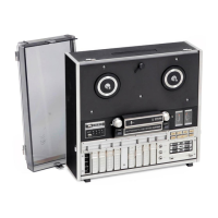
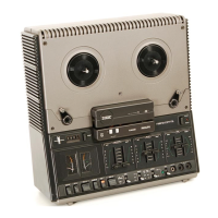
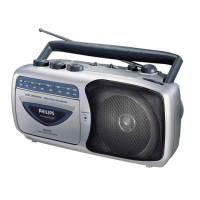
Details controls and indicators on the front of the unit.

Rear Panel Connections

Details connections and switches on the rear of the unit.

Mains Voltage and Frequency Switching

Audio Section Functional Units

Micro Input Unit (P1/P101)

Details the micro input circuit and its connections.

Universal Input Unit (P2/P102)

Describes the universal input circuit and its connections.

Playback Unit (P3/P103)

Details the playback circuit and its connections.

Further Functional Units

Recording Unit (P4/P104)

Details the recording circuit and its connections.

Before Tape Unit (P5/P105)

Describes the circuit before the tape transport and its connections.

Indicator Unit (P6/P106)

Details the indicator circuit and its connections.

Tone Control and Output Stages

Tone Control Unit (P7/P107)

Details the tone control circuit and its connections.

Power Output Unit (P8/P108)

Describes the power output circuit and its connections.

Oscillator Unit (P9)

Details the oscillator circuit and its connections.

Pre-Emphasis and Speed Selection Unit

Pre-Emphasis/Speed Selector Unit (P10)

Details the pre-emphasis and speed selection circuit.

Control Section Description

Control Logic and Flip-Flop Operation

Describes how buttons trigger flip-flops and control tape transport functions.

Button Functionality and Interlocks

Explains the operation of individual buttons like SK601, SK603, etc.

End Stage Short Circuit Protection

Control Unit Circuitry Details

Reset/Automatic Reverse Unit (P201)

Details the reset and automatic reverse functions and circuitry.

Motor Stop Unit (P202)

Describes the unit that stops motors during tape transport operations.

Tape Tension Control Units

Rightward Tape Transport Tension

Details tape tension control for rightward movement.

Leftward Tape Transport Tension

Details tape tension control for leftward movement.

Speed and Flip-Flop Logic Units

Flip-Flop Logic Units (P205/P206)

Explains the function of the flip-flop units in the control logic.

Speed Control Unit (P207)

Details the speed control mechanism for the capstan motor.

Hall Motor Operation

Hall Generator and Rotor Position

Describes the Hall element's function in detecting rotor position.

Hall Motor Control Circuitry

Explains the electronic control of the Hall motor speed.

Related product manuals