21
Range
Attenuation
RANGE
RNGB
RNGA
Input
ADC Ri
Pful
2517
E
F ET switch
v
201
10 v__
100
v-
1000
v-
10
10
'1000
1000
0
0
1
1
0
1
0
1
0.1 v
0.1
v
10
l\,lQ
10
lvro
I
tvt
0'l
9 t\,1 0'l
---o--
--r'o-
_+
_a-<-
o
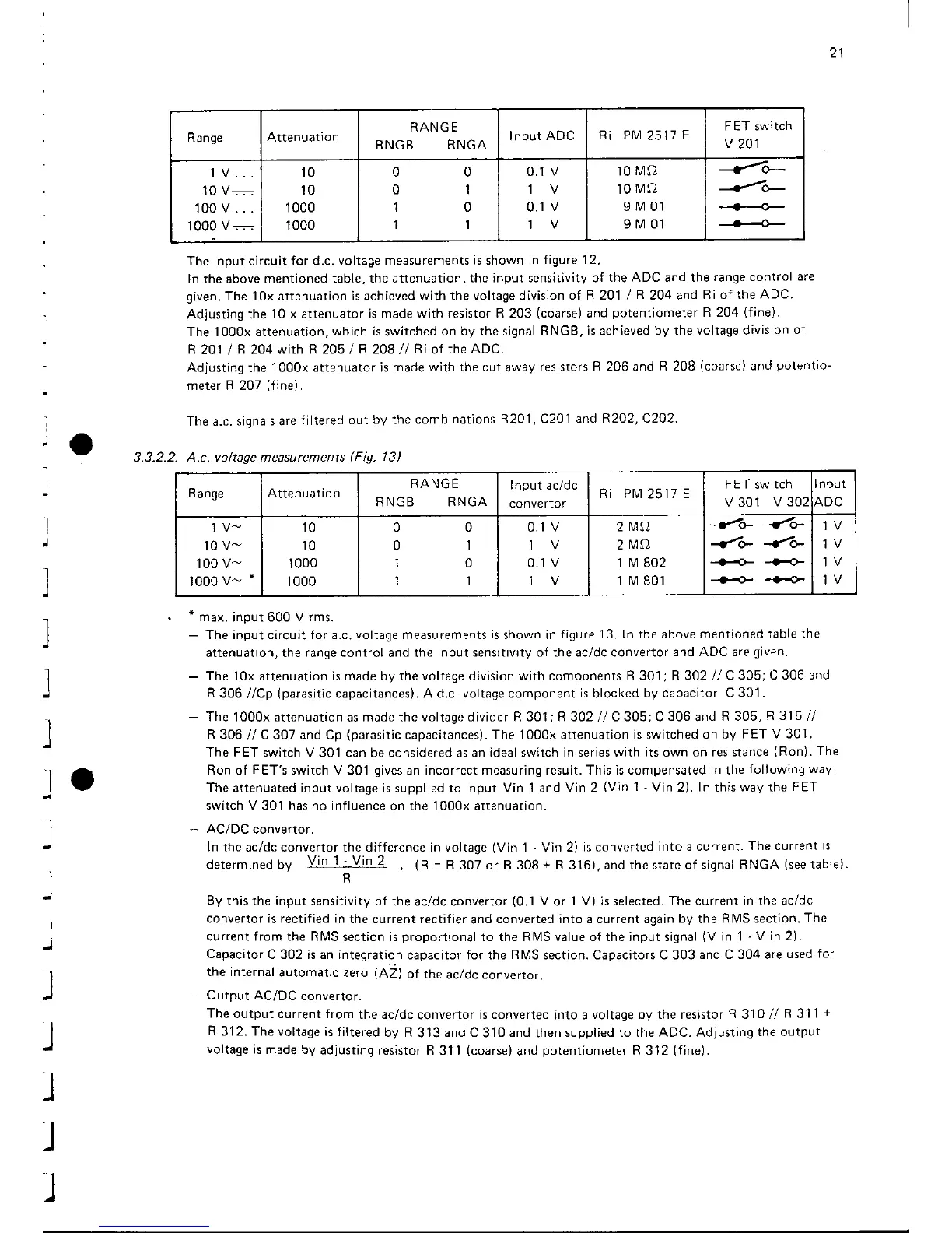
The input circuit
for d.c.
voltage measurements is shown
in figure 12.
ln the above
mentioned table, the attenuation,
the input sensitivity of
the ADC and the
range control
are
given.
The 10x attenuation
is
achieved
with the voltage
division of R 2O1
I
R
2O4 and
Ri of the
ADC.
Adjusting the
10 x attenuator is
made with resistor R 203
(coarse)
and
potentiometer
R 204
(fine).
The lOOox attenuation,
which is
switched
on by the signal
RNG8, is achieved by the
voltage division
of
R
201 /
R
204
with R 205
/
R 208
ll
Ri
of
the ADC.
Adjusting
the
IOOOX attenuator is
made with the cut
away
resistors
R 206
and
R 208
(coarse)
and
potentio-
meter R 207
(fine).
The a.c.
signals are
filtered
out
by
the
combinations
R2O1
,
C201 and
R2O2, C2O2.
3.3.2.2. A.c.
voltage measurements
(Fig.
13)
Range Attenuaiio n
RANG E
RNGB RNGA
Input acldc
convertor
Ri PM
2511
E
FET
switch
v 301
v 302
Input
ADC
10 v-
100 v-
1000
v-
'
10
10
1000
1000
0
0
1
1
0
l
0
I
0.1
v
1V
0.1 v
2l\ilQ
2MA
1
r\,1
802
1 r\4
801
-€o-
-{o-
-{o- -/o-
--..{--....o-
qH--}+-
1V
'
max.
jnout
600
V
rms.
-
The input circuit for a.c. voltage measurements is shown in
figure 13. ln the above
mentioned table the
attenuation, the
range
control and the
input sensitivity of the ac/dc convertor
and ADC are
given.
-
The 10x attenuation is made by the voltage division with components
R 301
;
R 302
//
C 305;
C 306 and
R
306
//Cp
(parasitic
capacitances). A d.c. voltage component
is
blocked
by capacitor C 301
.
-
The 1000x attenuation
as
made the voltage divider R 301; R 302
//
C 305; C
306
and
R 305;
R 315
//
R 306
//
C 307 and Cp
(parasitic
capacitances). The 1000x attenuation
is switched on by
FET V 301.
The FET switch V 301 can
be
considered as an ideal switch in series with
its
own on
resistance
(Ron).
The
Ron of FET's
switch
V
301
gives
an incorrect
measuring result. This is compensated
in
the
following
way.
The
attenuated input voltage is supplied to input Vin
1
and
Vin 2
(Vin
1
-
Vin
2).
In
this
way the
FET
switch V 301 has no influence
on the 1000x attenuation.
-
AC/DC
convertor.
In the
ac/dc convertor the difference in voltage
(Vin
1
'Vin
2)
is converted
into a current.
The current
is
determrned
by
Vin 1-Vin 2
.
(R
=
R 3O7or R 308+
R
316),and the srate
of signal RNGA
(seetabre,.
R
By
this the input sensitivity of
the acldc convertor
(0.1
V
or
1 V) is selected. The current
in
the
acldc
convertor is rectified in
the current rectifier
and
converted into a current again
by
the
R l\,4S section.
The
current from the Rl\4S
section is
proportional
to the RIVIS value of the input signal
(V
in 1
-
V
in
2).
Capacitor
C 302 is an integration
capacitor for the
RIVIS
section. Capacitors C 303 and
C 304 are
used
for
the internal
automatlc zerc
(AZl
of the
ac/dc
convertor.
-
Output AC/DC
convertor.
The
output current from
the ac/dc
convertor
is
converted into a
voltage by the resistor
R
310 //
R
311
+
R
312. The voltage
is filtered
by R
313
and C
310
and
then
supplied to the ADC. Adjusting
the output
voltage
is made by
adjusting
resistor R 3l1
(coarse)
and
potenriometer
R 3'12
(fine).
lo
J
J
l
J
J
I
)
J
l