28
-;
r1
"t
3.3.
2. 7. Temperatu
re measu
rements
[_,
t-r
iH-PROSE
3.^:
0
4:
lY-
t
t
t
t
e
t
t
t
t
t
t
,*,
1;).
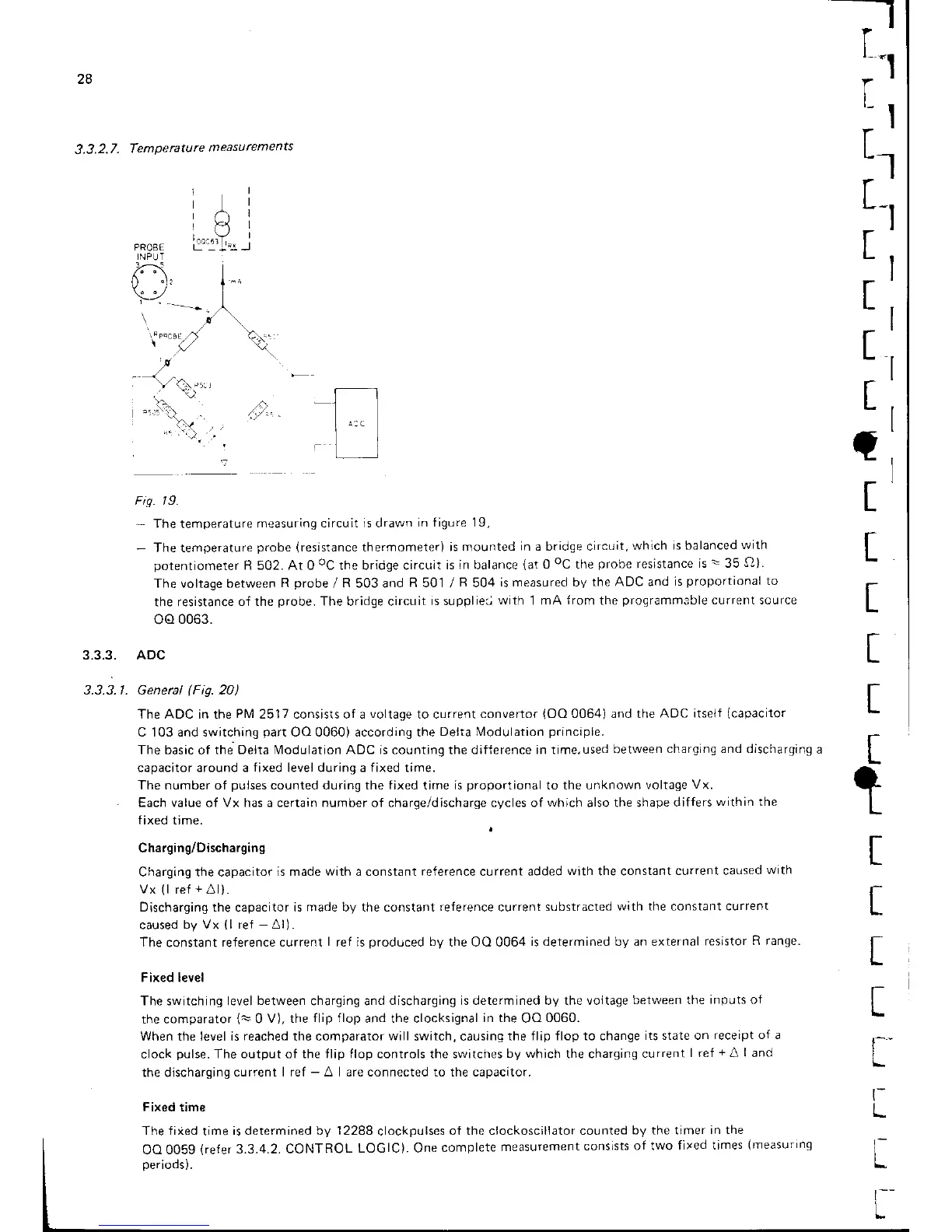
Fis. | 9.
-
The
temperature
measuring circLlit
is drawn
in figure 19,
-
The temperature
probe
(resistance
thermometer)
is mounted
in a bridge circLlit,
which
is balanced
with
potentiometer
R 502. At O
oC
the bridge circuit
is in balance
(at
0
oC
the
probe
resistance
is:35
5)).
The voltage between
R
probe
/
R
503 and
R 501
/
R
504
is measured by
the ADC and
is
proporfional to
the resistance
of the
probe.
The bridge circuit
is suppliea
with 1 mA
from
the
programmible
curr-"nt source
oo
0063.
3.3.3. ADC
3.3.3.1. Genercl
(F
ig. 20)
The ADC in
the
PN4
2517 consists of a
voltage
to current
convertor
(OO
0064) and the
ADC itselt
(capacitor
C 103 and switchinq
part
OO 0060) according the
Deita Modulation
principle.
The
basic of
the Delta Modulation ADC is counting the dif{erence in time,
used between
charging and dischargrng
a
capacitor around a
fixed
level during a fixed time.
The number of
pulses
counted during the fixed time is
proportional
to the unknown
voltage
Vx.
Each value of Vx has a certain number of charge/discharge cycles of
which
also the shape
differs
within the
fixed time.
Charging/Discharging
Charging the capacitor
is made
with
a constant
re{erence
current added
with
the constant
current caused
with
Vx
(l
ref
+
Al).
Discharging the
capacitor
is made by the constant
reference
current
substracted
with the
constant
current
caused
by Vx
(
I ref
-
AI) .
The
constant
reference current
I
ref is
produced
by
the OO 0064
is determined by an external
resistor
R range.
Fixed level
The switching level
between
charging and
discharging is determined by
the
voltage
between the
inputs ol
the comparator
(,=
0
V), the
flip ilop
and the clocksignal
in the
OO
0060.
When the level is
reached
the comparator
will
switch, causing
the flip flop to change
its state on
receipt of a
clock
pulse.
The output of the llip flop controls the switches
by which
the charging
current
I ref
+
A
I
and
the discharging current
I ref
-
A I are connected to the capacitor.
Fixed
time
The fiied
time
is determined by 12288
clockpulses
of the clockoscillator counted
by the timer
in the
oo 005g
(refer
3.3.4.2. CONTROL
LOGIC). One
complete
measurement
consists
of two
fixed times
(measurrng
oeriods).
t
r
L
t
I
t_
t-
L