3.3.2.5. Besistance
measurements
(Fig.'s
16. 17 and 18)
-
The resistance
measuring circuit is drawn
in figure 16.
-
A known constant current
which is supplied
bV
the
programmable
current
source OO 0063
flows through
the un known resistor
RX.
Dependent to the range
(manual
or automatic
selection) the currents
are selected
by the signals
R NGA,
R NGB and
R NGC
(see
table).
r.
r
I
26
t
t
t
t
r,
['
t
t
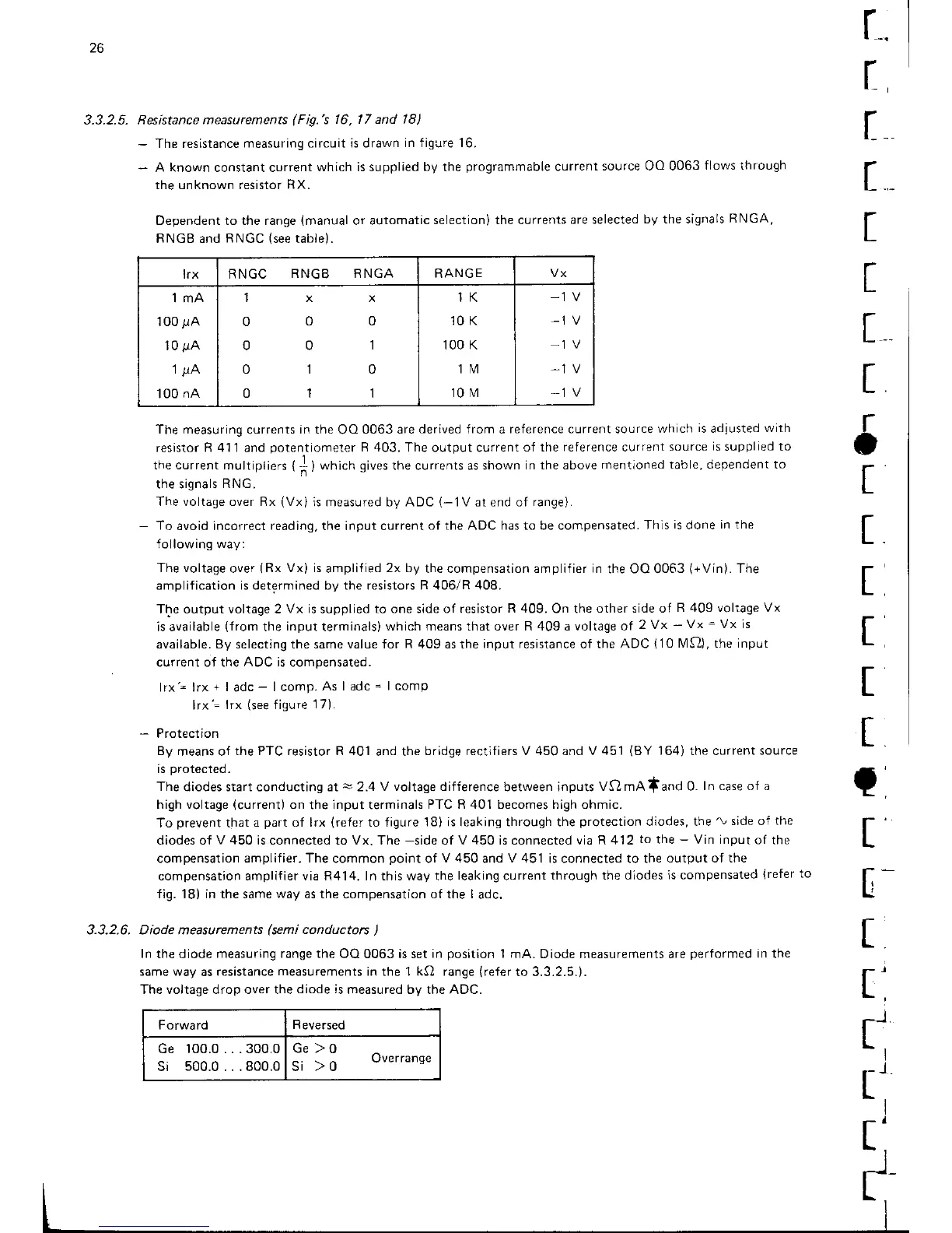
trx RNGC
RNGB RNGA RANGE
lmA
100
r1A
10
gA
1
,uA
100
nA
txx
000
001
010
011
1K
10 K
100 K
1M
10 M
-1
V
-1
V
,1
V
-1
V
Forward
R
eversed
Ge 100.0...300.0
si
500.0...800.0
Ge )0
si > o
uverrange
The measuring
currents
in the
OO
0063 are
derived {rom
a
reference current source
which
is
adiusted
with
resisto(
R 4'11
and
potentiometer
R 403.
The output current
of the reference current
source
is
supplied to
the current
multipliers
{] )
wfricfr
gives
the currents as shown
in the above
mentioned table, dependent to
the signals
RNG.
The voltage over Rx
(Vxi
is measured by ADC
(-1V
at end of
range).
-
To
avoid incorrect
reading,
the input current
of the ADC has to be compensated.
This
is
done
in the
f ollowing way:
The voltage
over
(Rx
Vx) is
amplified
2x by
the compensation ampliiier in
the OO 0063
(+Vin).
The
amplification
is determined by the resistors R 406/R 408.
The output voltage 2
Vx is
supplied
to one side of resistor
R 409.
On the
other side of
R 409 voltage Vx
is available
(from
the
input
terminals)
which means lhat over R 4Og a voltage of
2 Vx
-
Vx
=
Vx is
available. By selecting the same value for
R
4Og as the
input resistance
of
rhe ADC
110
lMf2),
the
input
current of the
ADC
is compensated.
lrx'= lrx
+
|
adc-
| comp.
As I adc
=
| comp
lrx'=
lrx
(see
figure
17).
-
Protection
By
means of
the PTC resistor R 401
and the
bridge rectifiers V 450 and V 451
(BY
'164)
the current
source
is
protected.
The
diodes start conducting at
-
2.4
V voltage difference
between inputs
Vf)mAland 0.
In case of a
high voltage
{current)
on
the
input
terminals
PTC R 401 becomes high ohmic.
To
prevent
that
a
part
of lrx
(refer
to figure
'lB)
is leaking through the
protection
diodes, the'v
side of
the
diodes of
v
450 is connected to vx. The
_side
of v 450 is connected uia R 412
to
the
_
vin input
of the
compensation amplifier.
The
common
point
of
V
450 and
V
451 is connected to the
output of the
compensation amplifier via R414. In this way the
leaking
current
through the diodes
is compensated
{refer
to
fig. 18) in the same
way
as the compensation of the I
adc.
Diode measurements
(semi
conductors
)
In
the diode
measuring range the
OO 0063 is set
in
position
1 mA. Diode measurements are
performed
in the
same way
as
resistance
measurements
in the 1 kQ range
(refer
to 3.3.2.5.).
The voltage drop over the
diode is
measured by the ADC.
t
5
t
t
t
t
t
t
r
t
[-
3,3.2.6.