45
5
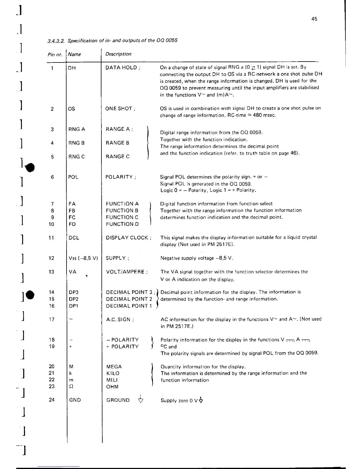
3.4.3.2-
Specification
of in- and
outputs of the OO 0055
Description
DATA
HOLD
;
On a change of state
of signal
RNG
a
(0
Z
1) signal DH
is
set.
By
connecting the output DH to OS
via a RC'network
a one shot
pulse
DH
is created,
when
the
range information
is
changed.
DH is used
for the
OO 0059 to
prevent
measuring until the
input amplifiers are
stabilised
in
the
functions V-
and
{m)A-.
OS
is used in combination
with signal DH to create
a one shot
pulse
on
change
of range information.
RC-time
!
480
msec.
Digital
range information from
the
OO 0059.
Together with the function indication.
The range information determines the decimal
point
and the function indication
(refer.
to truth table
on
page
46).
Signal
POL determines the
polarity
sign.
+
or
-
Signal
POL
is
generated
in the
OO 0059.
Logic Q
= -
Polarity, Logic 1
=
+
Polarity.
Digital function
information from function select
Together with the range information
the function
information
determines
iunction indication and the
decimal
point.
This signal
makes the display information suitable
for a
liquid crystal
display
(Not
used in
Plvl
2517E).
Negative supply
voltage
-8,5
V.
The
VA
signal together
with the function selector determines the
V
or A indication
on the display.
;)
Decrmal
pornt
informatron
for
the
display. The
informarion is
I
)
determined by the
function-and
range
information.
I
AC information for the display
in
the
functions V- and
A-.
lNot
used
in
Pl\4
2517E.)
Polarity information for the display in the
functions
V
-..=-,
A
--
oC
and
The
polarity
signals are
determined by signal
POL from the
OO 0059
Ouantity information for the display.
The information is determined by the
range information and
the
function information
RNG A
RNG B
RNG C
FA
FB
FC
FD
DCL
Vss
(-8,5
V)
DP3
DP2
DP1
FUNCTION A
FUNCTION B
FUNCTION C
FUNCTION D
D ISPLAY CLOCK
ONE SHOT
;
RANGE
A;
RANGE B
RANGE C
POLARITY;
SUPPLY;
VOLT/AN,4PERE;
D
ECII\4AL POINT
DECIIVIAL POINT
DECII\4AL
POINT
A.C.
SIGN
;
_
PO LA R ITY
+
POLAR ITY
la
-l
I
I
l
l
I
l
J
12
1
8
10
1l
20
22
23
24
ta
l
I
_l
l
-t
J
I
-t
14
t5
to
17
18
19
3
2
1
I\4 EGA
KILO
t\i1tLl
oHtvl
I
GROUND
V
Supptyzero0V$