Circuit Descriptions
EN 51Q549.2E LA 7.
2009-May-08
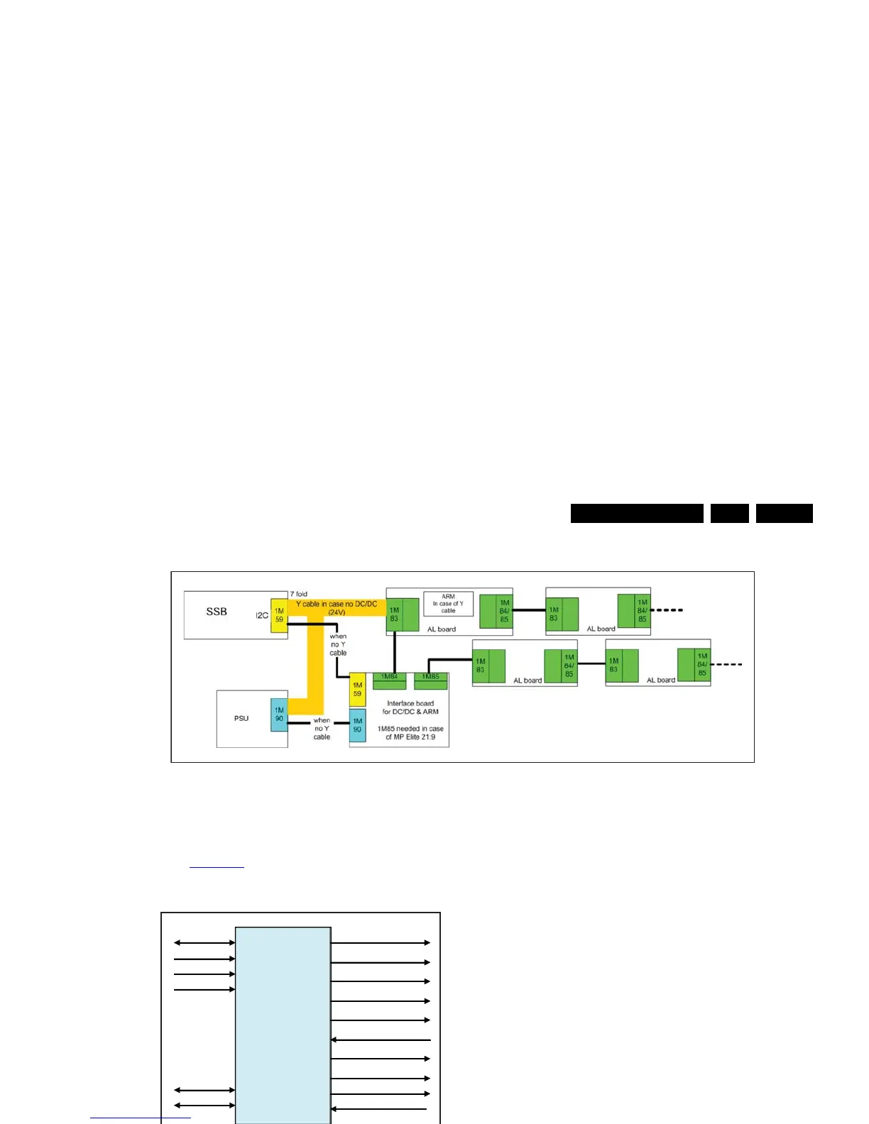
Figure 7-12 Interface between Ambi Light and SSB
7.8.1 ARM controller
Refer to Figure 7-13
below for signal interfacing to and from the
ARM controller. The ARM controller is located on the DC/DC
board (item no. 7302) or AL panel (item no. 7102).
Figure 7-13 ARM controller interface
Data transfer between ARM processor and LED drivers is
executed by a Serial Peripheral Interface (SPI) bus interface.
The SPI bus is a synchronous serial data link standard that
operates in full duplex mode.
For debugging purposes, the working principle is given below:
• At startup the controller will read-out matrix data from the
EEPROM devices (via SPI DATA RETURN)
• Before operation, the driver current is set via SPI, with
driver in DC mode
• During normal operation the controller receives RGB-,
configuration-, operation mode- and topology data via I
2
C
• The controller converts the I
2
C RGB data via the matrixes
to SPI LED data
• Via data return the controller receives error data (if
applicable).
Also PWM clock and BLANK signals are generated by the
controller. The controller can be reprogrammed via I
2
C (via
USB). The controller can receive matrix values via I
2
C, which
will be stored in the EEPROM of each AL module via the SPI
bus. The temperature sensor in each AL module controls the
TEMP line; in case of a too high temperature the controller will
reduce the overall brightness.
7.8.2 LED driver communication (via SPI bus)
Refer to Figure 7-14
below for signal interfacing between the
ARM controller and the LED drivers on the AL boards, and the
LED drivers and the EEPROMs on the AL boards.






 To Next Page