Mechanical Instructions
EN 20 SDI PDP4.
4.1.4 Exchange of LBE, LBF, LBG board
1. Depending on the model (see “Photo 2” per model.):
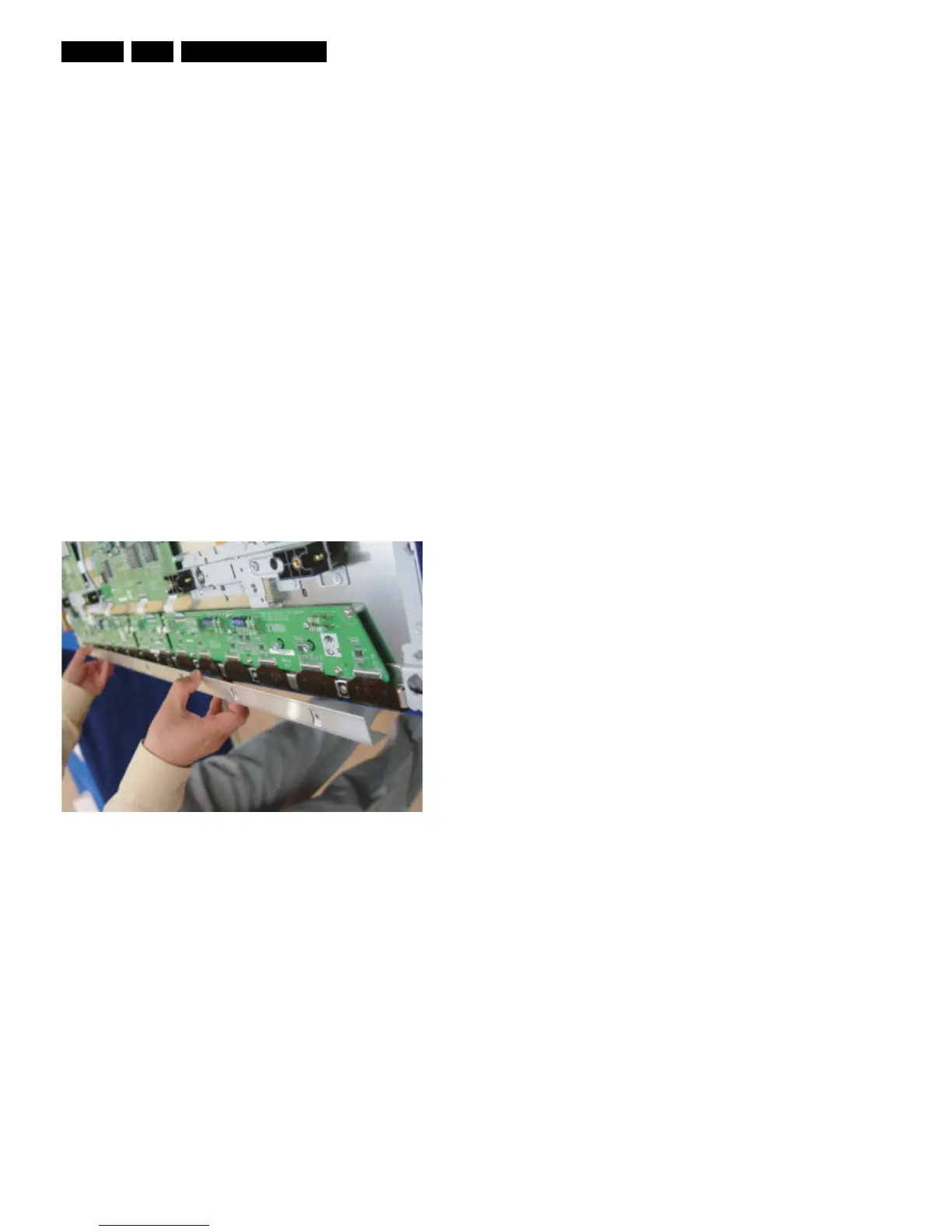
– 42" SD v3 - Remove the screws in order of 2-3-5-7-1-
4-6 (and 10-11-13-16-9-12-14 for HD) from heat sink
and then remove heat sink (Photo 1).
– 42" SD v4 - Remove the screws in order of 2-4-1-5-3
from heat sink and then remove heat sink (Photo 1).
– 42" HD v3, 37" SD v4, 50" HD v3 - Remove the
screws in order of “Centre - Left Side - Right Side” from
heat sink and then get rid of heat sink (Photo 1).
– 50" HD v4 - Remove the screws in order of 2-3-1-4
from heat sink and then remove heat sink (Photo 1).
2. Remove the TPC, FFC, and power cable from the
connectors.
3. Remove all the screws from the defective board.
4. Remove the defected board.
Note: When replacing the Logic board or Y-main board for
a lead-free (Pb-free) board, always replace them together.
(this is only valid for the 37” SD v4 displays!)
5. Replace the new board and then screw tightly.
6. Clean the connectors.
7. Re-connect the TCP, FFC, and power cable to the
connector.
8. Re-assemble the TCP heat sink. Use the same screw
mounting order as described above
Caution: If you screw too tight, it is possible to damage the
Driver IC of the TCP.
Figure 4-9 Photo 1 - Heatsink removal