Service Modes, Error Codes, and Fault Finding
EN 33SDI PDP 5.
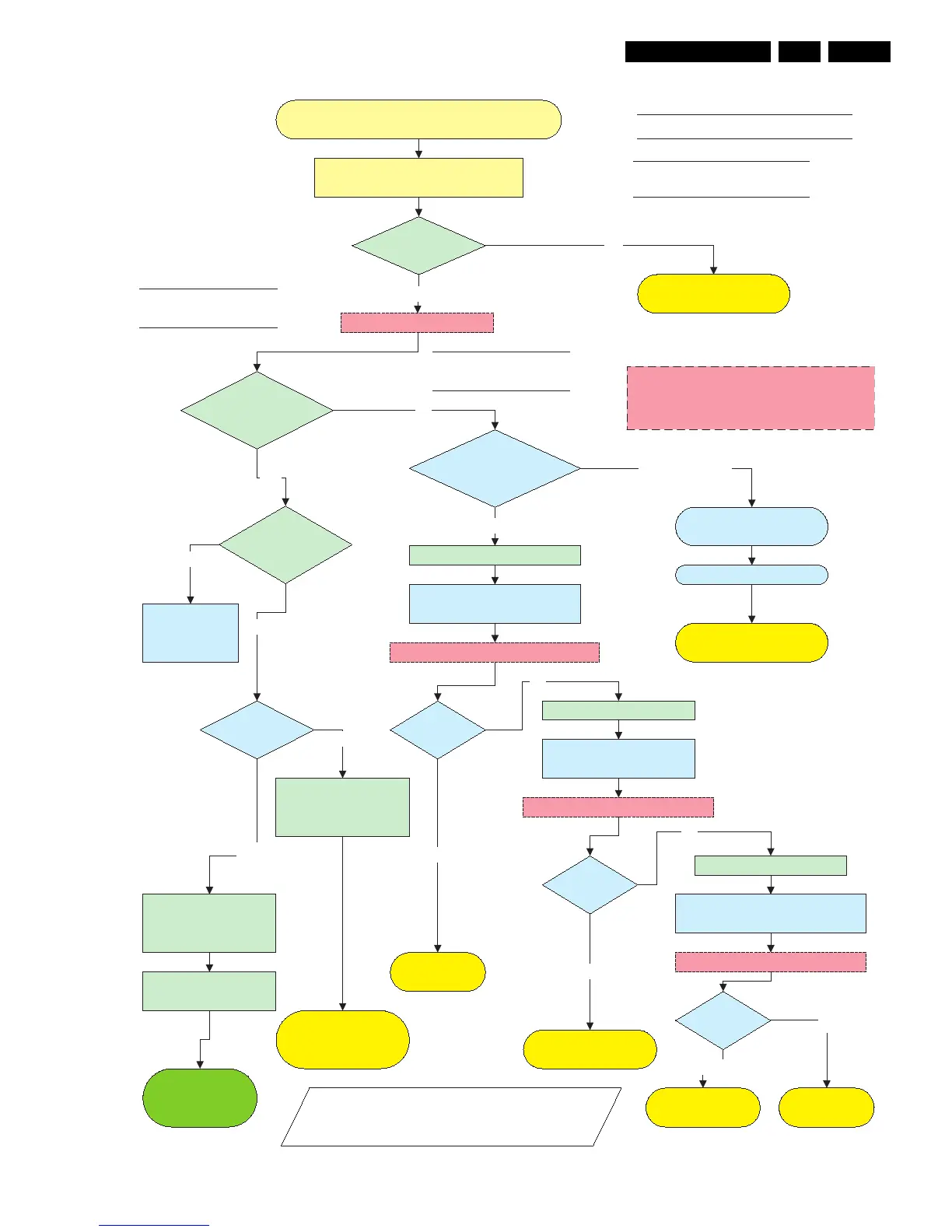
Figure 5-11 Power Supply Check for v3 models
Check CN8001 / 2pin connector 220V AC
Power Supply Check (v3 versions)
LED8003
Stby is ON?
Green LEDs
8001, 8002
are ON?
Connect set to mains.
Check SMPS outputs
Vs, Va, Vset, Ve, Vsc
see Sticker
Ye s
NO
Check Fuse F800 / F8002 / F8003
ON/OFF relay
RLY8001/8002 acts?
Switch ON via 1 or 2
Check Protection Red
LED8004
Ye s
No
Disconnect VA Logic Buffer
CN8005 / CN800x
Disconnect X-main CN8002
SMPS shutsdown?
Red LED8004 is on.
Protection
Reconnect mains. Switch ON via 1 or 2
Standby supply is defective.
Replace PSU
Ye s
Activate SAM
or SDM
Disconnect mains cord
Disconnect Y-main CN8003
SMPS is
working?
Disconnect mains cord
No
Disconnect mains
Reconnect mains. Switch ON via 1 or 2
SMPS is
working?
No
Replace
Y-Main board
Replace
X-Main board
SMPS is
working?
No
Replace defective
Logic Buffer board
Ye s
Reconnect mains. Switch ON 1 or 2
Replace PSU
Ye s
Check Stanby Line pin 13
on CN8004 must be LOW.
Go to repair
scenario
as stand-alone
LEDs 3.3V and 5V
on Logic main board?
Data communication from
Philips application to Logic
mains is OK.
Blinking
Continous on, means no
data communication over
LVDS Cable.
On
Green LED 8001,
8002
& Red LED are OFF
Ye s
Discharge capacitors on Power supply,
before reconnecting X, Y or Logic Buffer
board, use 2K4/10W discharge resistor
No switch ON of PSU
Switch from standby to on;
1 Via RC when Philips application is in.
2 Via Switch-On-Jig connector when Philips
application is removed
Check Power
supply on Logic-
Main board.
Data LED ON
Logic Main ?
On
Off
Go to repair scenario
as stand-alone