Philips Semiconductors
TDA1562Q application note
Koninklijke Philips Electronics N.V.
Application note Rev. 01.02 — 05 May 2006 20 of 62
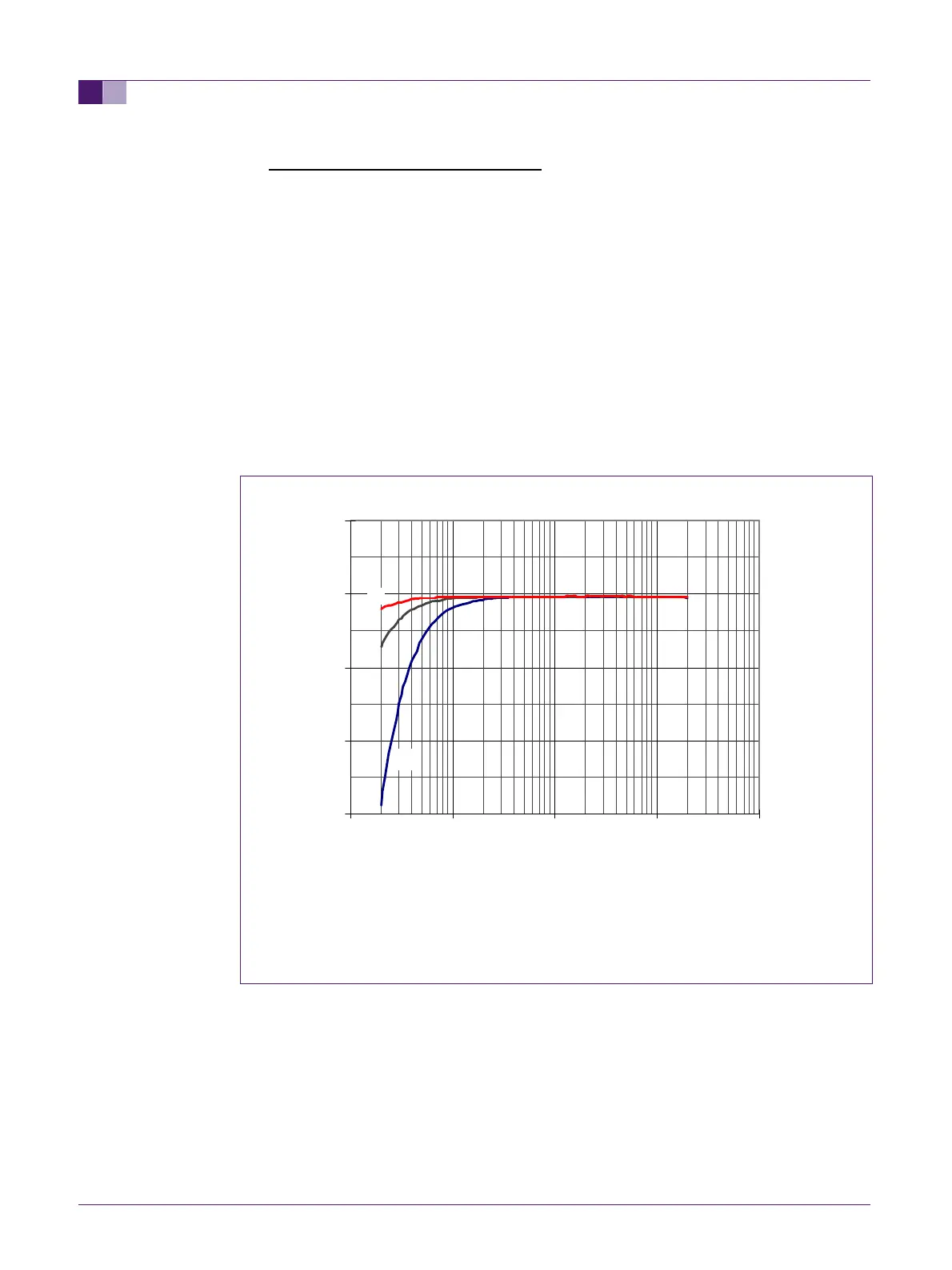
• The input capacitors Cin1 and Cin2:
These capacitors are necessary to obtain a DC separation between the inputs and
the signal source. The capacitance of the input capacitors, combined with the input
impedance of the amplifier determines the low frequency roll-off point.
In the standard application a value of 100nF is used for these capacitors, higher
capacitances will result in a lower roll-off frequency (see also fig.8). It is advised to
use capacitors with a low DC leakage (film capacitors) for this purpose, since any DC
leakage at the inputs will result in a DC offset at the outputs. Electrolytic capacitors
usually have a relatively high DC leakage current, so they should not be used as
input capacitors.
As already mentioned, the TDA1562 has a symmetrical input. In order to achieve the
highest possible suppression of common mode interference, the two input capacitors
should be well matched. Especially at low frequencies the difference in impedance
between two nominally equal capacitors may cause a deterioration of the CMRR
(common mode rejection ratio). Fig. 9 shows the effect of the input capacitors on the
CMRR.
A: 100nF input capacitors
B: 220nF input capacitors
C: 470nF input capacitors
Fig 8. Low frequency roll off with different values of input capacitors
23
24
25
26
27
0.01 0.1 1 10 100
F(kHz)
Gv(dB)
A