Philips Semiconductors
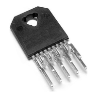
TDA1562 application note
Koninklijke Philips Electronics N.V.
Application note Rev. 01.02 — 05 May 2006 61 of 62
10. Contents
1. Introduction.......................................................3
1.1 Amplifier description..........................................3
1.2 The Class H principle........................................3
1.3 Block diagram...................................................6
1.4 Pinning.............................................................7
1.5 Quick reference data.........................................8
2. Features and Diagnostics.................................9
2.1 The Mode select pin..........................................9
2.2 The Status I/O pin.............................................9
2.3 The diagnostic pin...........................................10
2.4 Differential inputs............................................14
3. Switch on/off behavior....................................14
4. Protections and overstress conditions ..........16
5. Application description...................................18
5.1 Application schematic.....................................18
5.2 Dimensioning of the Class H application..........23
5.3 Minimum load impedance ...............................28
5.4 Recommendations..........................................28
5.5 Used components...........................................29
5.6 PCB lay out ....................................................30
5.7 Thermal behavior............................................32
5.7.1 Power dissipation............................................32
5.7.2 Power dissipation curves.................................33
5.7.3 Heatsink calculation........................................35
6. Typical waveforms..........................................37
7. Measurement curves.......................................45
8. Driving a dual voice coil speaker....................49
8.1 Pulses below substrate level at the outputs......49
8.2 Positive voltage pulses at the outputs..............52
8.3 Protection circuits ...........................................55
8.3.1 Hard limiter.....................................................55
8.3.2 OVP circuit.....................................................57
8.4 Load detection for subwoofers with very large self
inductance.....................................................................57
9. Conclusion......................................................60
10. Contents..........................................................61