Philips Semiconductors
TDA1562Q application note
Koninklijke Philips Electronics N.V.
Application note Rev. 01.02 — 05 May 2006 38 of 62
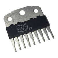
The lower half of the sinewave at each output will start clipping, as is illustrated in figs. 23
and 24.
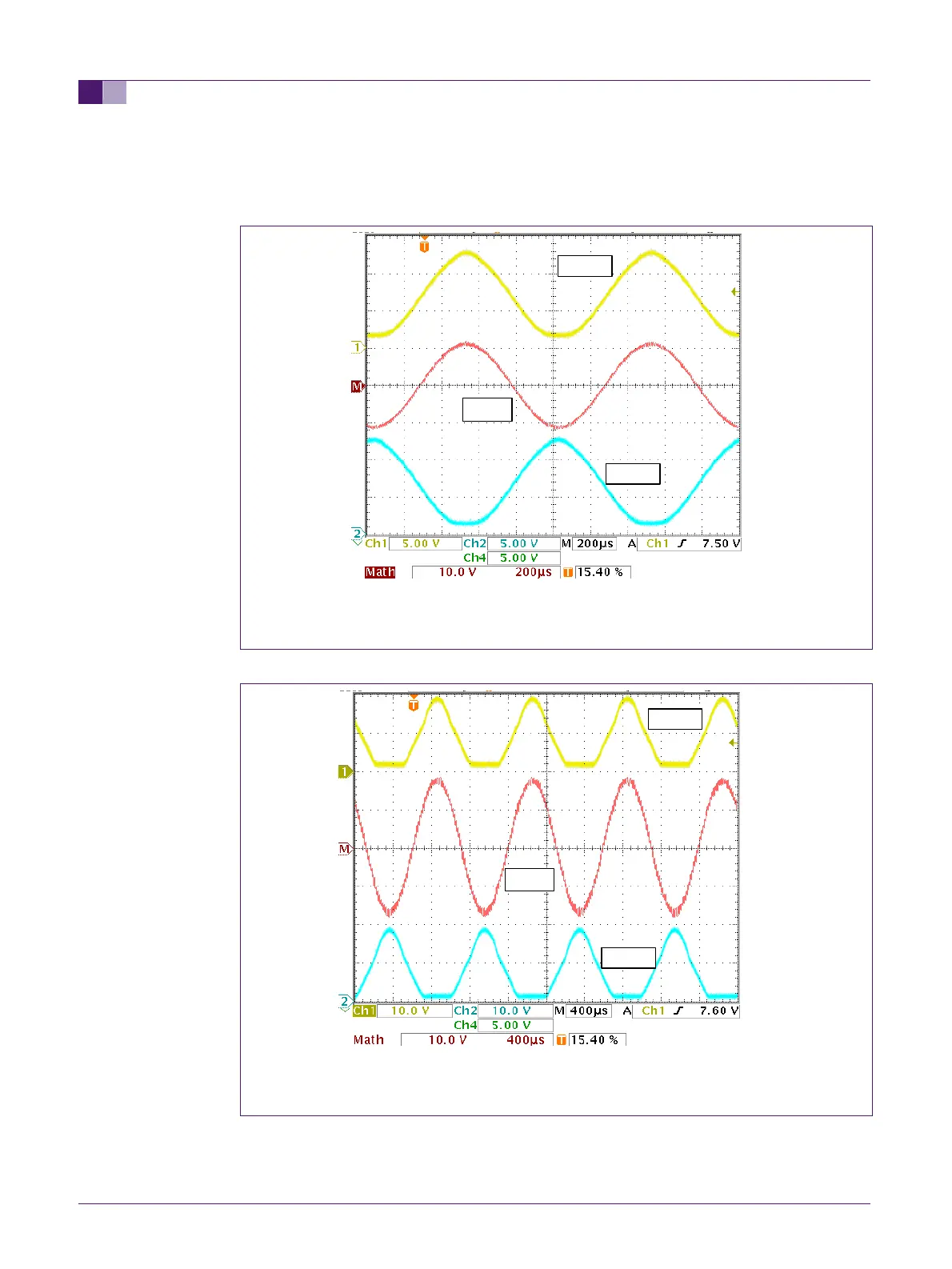
Fig 23. Output signals at low level lifting (f=1kHz)
Fig 24. Output signals at high lifting level (f=1kHz)
Figure 23 shows the shape of the signals at both outputs when the amplifier just starts
lifting the supply. It is visible that the tops of the sine waves are becoming slightly
“sharper” and it is also visible that the bottom part of the sinewaves starts “flattening”
OUT 1
OUT 2