Philips Semiconductors
TDA1562Q application note
Koninklijke Philips Electronics N.V.
Application note Rev. 01.02 — 05 May 2006 41 of 62
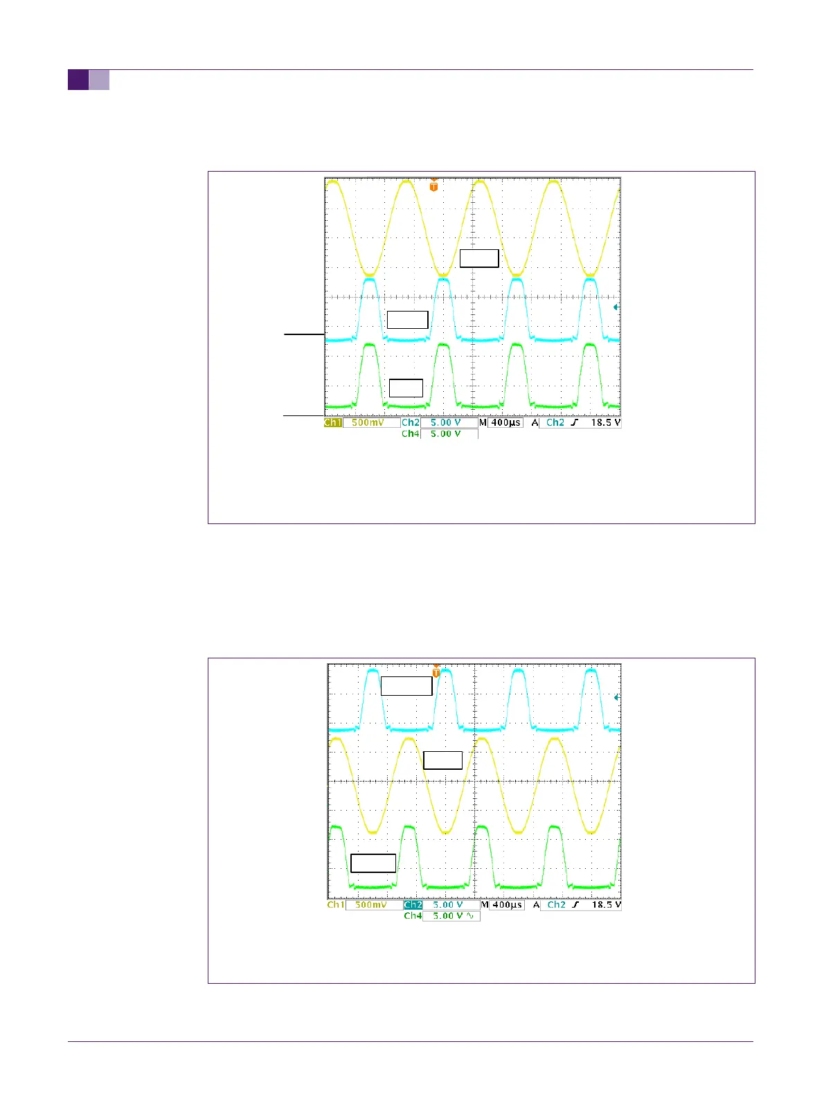
The wave forms which can be observed at the lift capacitors also illustrate the way the
TDA1562 works and its limitations.
Fig 27. Waveforms at the + and – terminals of one lift capacitor
When the amplifier starts lifting, the voltage at the negative terminal of the lift capacitors
will be lifted, thus lifting the voltage at the positive terminal. Figure 27 shows the
waveforms at the + and – terminals of one of the lift capacitors during lifting.The lowest
voltage level at the –terminal is slightly above 0V, which is the saturation voltage of
transistors T7 and T8 (see fig. 1). The lowest voltage level at the +terminal will be
approximately one diode forward voltage below the supply voltage (due to diodes D1 and
D2).
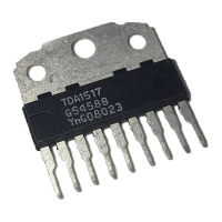
Fig 28. Waveforms at the + terminals of both lift capacitors
Since there are two output stages, there are two lift capacitors, each taking care of one
half of the sine wave. This is illustrated in figure 28.
Clift +
Vload
Vload