F8
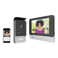
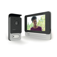
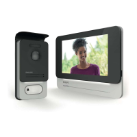
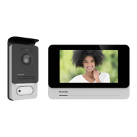
WelcomeEye Connect 2 / Touch / V4
6 – Connect the two intercom panel wires and the two power supply wires following the
wiring diagram.
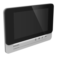
7 - Position the monitor on the wall bracket.
8 - Depending on the conguration selected, and when wiring is completed, the interface
may have to be congured.
Warning: during this step, do not connect the power supply to the 230V AC.
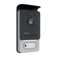
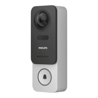
4. Installation of the main or additional intercom panel*
Warning: The product must not be connected to the power supply before the wiring has
been completed.
DES 9900 VDP
5 1 0 0 6 3
1
2
3
4
5
6
1 2
7
8
1
2
1
2
DES 9901 VDP
5 1 0 0 6 3
Made in P.R.C
IP44
20V 110mA
RFID 125kHz
1m60
1
1
2
2
1 2
4
7
5
3
6
8 9
Avidsen
19 avenue Marcel Dassault
37200 TOURS
FRANCE
1 - Remove the tamper-resistant screw from underneath the intercom panel, using the key
provided.
2 - Tip the intercom panel cover forward.
3 – The intercom’s lens should be approximately 1.60m above the ground.
4 – Mark the locations.
 Loading...