ILC 2050 BI
10 / 74
PHOENIX CONTACT 107144_en_01
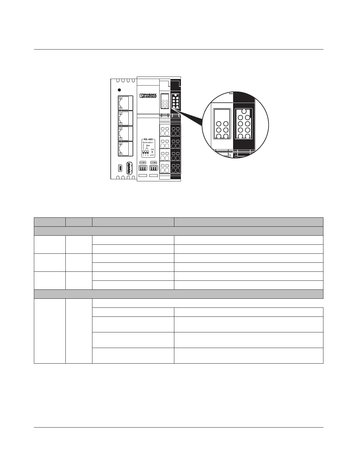
2.4 Diagnostic and status indicators
Figure 2-3 Diagnostic and status indicators
107144A010
SERVICE
Rx
1.1 2.1
1.2 2.2
1.3 2.3
1.4 2.4
1.1 2.1
1.2 2.2
1.3 2.3
1.4 2.4
Tx Rx
Tx Tx
Rx
1
Rx
2
COM
SV
SE UL
ST
UM
PL
IO
US
USB 1 USB 2
LAN 3LAN 4 LAN 1
L
AN 2
Tx
Rx
Tx Tx
Rx
1
Rx
2
COM
PL
US
ST
UM
SE
UL
SV
IO
ILC 2
050 BI
Table 2-1 Diagnostic and status indicators
Des. Color Status Meaning
Supply LEDs
US Green
Off No voltage present in the segment circuit.
On Voltage present in the segment circuit (+24 V DC).
UM Green
Off No voltage present in the main circuit.
On Voltage present in the main circuit (+24 V DC).
UL Green
Off U
BK
(24 V supply), U
L
(logic circuit) not OK
On U
BK
(24 V supply), U
L
(logic circuit) not OK
Process status LEDs
PL Yellow
Status of the Niagara platform
Off The process has not started.
Flashing with 2 s cycle duration,
10% (on): 90% (off)
The process is running and requires less than 10% of the pro-
cessor time.
Flashing with 2 s cycle duration,
50% (on): 50% (off)
The process is running and requires between 10% and 50% of
the processor time.
Flashing with 2 s cycle duration,
90% (on): 10% (off)
The process is running and requires more than 50% of the
processor time.

 Loading...


