ILC 2050 BI
8 / 74
PHOENIX CONTACT 107144_en_01
2.3 Connection and operating elements
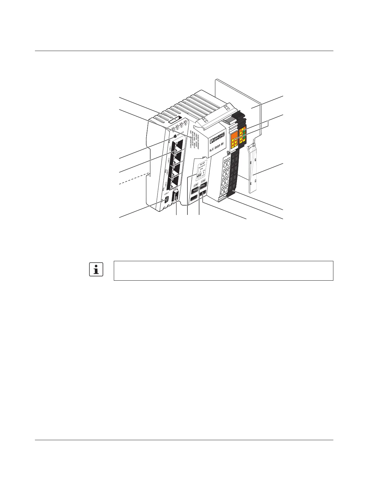
Figure 2-1 Structure of the Inline controller
1 Micro SD card slot
2 Imprint of the device-specific information
3 Service button
4 Ethernet interfaces (4 x 10/100Base-T)
5 Grounding contacts
1
6 USB interface 1 (mini USB, USB OTG)
7 USB interface 2 (type A)
8 Assignment of DIP switches (RS-485 Termination/Bias)
9 DIP switches (RS-485 Termination/Bias)
10 Service interface
11 Connector 1: bus connector
12 Connector 2: power connector
13 Marking field (2x)
14 Diagnostic and status indicators
15 End plate
RS-485 Termination/
Bias
RS-485 networks are executed in a bus topology and are terminated at both ends with a ter-
mination resistor between the data lines. Furthermore, the bus lines are brought once to a
defined quiescent level with bias resistors. The Inline controller has resistor networks for ter-
The micro SD card is not supplied as standard with the Inline controller.
Please refer to the ordering data in Section “Ordering data ILC 2050 BI(-L)” on page 59.
1
On the rear device side, not visible in Figure 2-1
COMCOMCOMCOMCOMCOMCOMCOMCOMCOMCOMCOMCOMCOMCOMCOMCOM
COM
COM
IO
Rx
PL
Rx
T
x
Tx
Tx
Rx
ST
UM
US
SV
107144A005
1
2
S
E
UL
15
1
3
4
5
78
12
6
2
13
14
9
10
11

 Loading...


