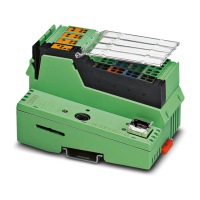
Description of the Inline controller
107144_en_01 PHOENIX CONTACT 7 / 74
2 Description of the Inline controller
2.1 General description of the Inline controller
The ILC 2050 BI (-L) Inline controller is a modular small-scale controller for Niagara and
Sedona. A special feature of the Inline controller is its scalability, which involves several as-
pects:
–Scalable I/Os
The Inline controller is a head station for the modular Inline terminal system. You can
connect up to 63 Inline terminals to an Inline controller. To this end, a variety of terminal
types is available, ranging from digital and analog inputs and outputs with different num-
bers of channels right through to function terminals for DALI, pulse width modulation,
M-Bus, or serial interfaces.
–Scalable software
The Inline controller has been designed for use with the Niagara Framework
®
(herein-
after referred to as Niagara). Niagara applications, known as Niagara stations, are cre-
ated with the Niagara Workbench software tool.
Niagara's modular nature means its applications are able to fulfil an incredibly wide
range of completely different project-specific requirements. If necessary, it is also pos-
sible to program your own separate modules and use them in the application.
– Scalable licensing
The license model for Niagara is very flexible: a number of data points are licensed,
which are integrated with the Inline controller.
The license packages are available as initial licenses (250/500/1250/5000/10,000 data
points) or as upgrade licenses (500/1250/2500 data points).
–Scalable IP network
The Inline controller has two IP interfaces that are logically separated from each other,
and an integrated Ethernet switch with a total of four external interfaces. Thanks to the
configurable assignment of Ethernet interfaces to the two IP interfaces that are sepa-
rated from each other and the use of the spanning-tree protocol, flexible topologies
such as daisy chains and redundant ring structures are possible in the backbone net-
work and in the local controller network.
2.2 Processor core
– Processor: ARM
®
Cortex
®
-A8/1 GHz
– DDR3 SDRAM: 1 GB RAM (512 MiB for HW version <06, see series label)
–eMMC flash: 1.8GB
– SRAM: 512 KiB (buffered for 5 days in the event of voltage failure)
– RTC: buffered for 5 days in the event of voltage failure
A micro SD card slot enables the internal flash memory to be expanded.
The ILC 2050 BI and ILC 2050 BI-L controllers look exactly the same, differing in just a
few details and functions. Hereinafter, therefore, this document uses the general terms
controller, bus controller, Inline controller, or ILC 2050 BI (-L). Any specific differences are
indicated in the corresponding sections of the text where necessary.

 Loading...


