2.4. Blindaje del cable de datos
Si se esperan corrientes compensadoras
de potencial, poner a tierra directamente
la malla solo en un lado y el otro lado a
través de un condensador (15 nF).
Conexión del blindaje
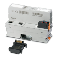
• Conector enchufable SUB-D (fig. 6)
El blindaje se efectúa a través del arma-
zón del conector SUB-D que está co-
nectado en fijo con el borne de equipo-
tencial en el módulo (conexión a tierra).
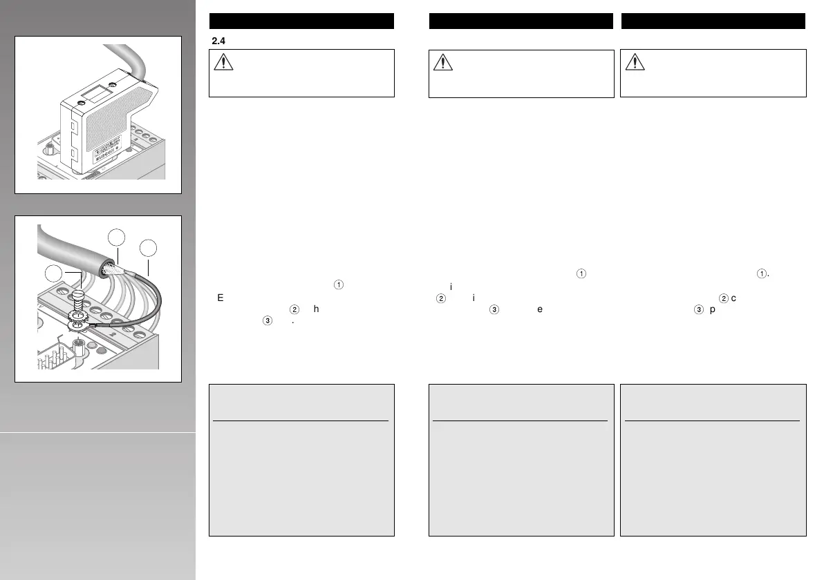
• Borne de tornillo (COMBICON) (fig. 7)
El blindaje se efectúa en el módulo PSM
con el juego de puesta a tierra adjunto
por medio de la rosca del tornillo del
armazón del conector SUB-D
1
.
Conectar eléctricamente el extremo libre
del cable de conexión
2
con la malla del
cable de datos
3
(p.ej. soldar, embor-
nar) según la figura 7.
3. El interface RS-232
3.1. Conexión de conductores
Más respecto al interface RS-232 en la pág. 17.
Utilizar cable blindado. Conectar
la malla del cable en ambos la-
dos de la línea de transmisión.
ESPAÑOL
14 15
Fig.7
RS 232
3
4
5
9
V 0V NC TxD
RxD CTS RTS GND
RS232
1 25 3
Fig.6
T
Y
T
Y
T
Y
T
Y
RS 232RS 232
1
2
3
4
5
6
7
8
9
2
4
V
0
V
N
C
T
x
D
R
x
D
C
T
S
R
T
S
G
N
D
R
S
2
3
2
Art.-Nr. 27 61 25 3
R+ R–
TTY
S1+ S1– S
PSM-EG-RS232/TTY-P/2K
2.4. Data Cable Shielding
If equipotential bonding currents are to be
expected, ground the shielding directly on
only one side and on the other side via a
capacitor (15 nF).
Shielded connection
• SUB-D plug connector (Fig. 6)
The shielding takes place via the SUB-D
connector frame, which is permanently
connected to the equipotential bonding
terminal on the device (ground terminal).
• Screw terminal block (COMBICON)
(Fig. 7)
On the PSM module, the shielded con-
nection is made with the enclosed
ground connection set via the screw
thread of the SUB-D frame
1
.
Electrically connect the free end of the
connection cable
2
with the shield of the
data cable
3
(e.g. by soldering, clamping)
according to Fig. 7.
3. The RS-232 Interface
3.1. Pin Assignments
Further details for the RS-232 interface,
see page 16.
Use shielded cables.
Connect the cable shield at both
ends of the transmission path!
ENGLISH
COMBI- SUB-D
Description CON 9-pos.
(from left) (male)
Supply voltage 24 V Pin 1 ––
0 V Pin 2 ––
Transmit data TxD Pin 4 Pin 3
Receive data RxD Pin 5 Pin 2
Clear to send CTS Pin 6 Pin 8
Request to send RTS Pin 7 Pin 7
Functional ground GND Pin 8 Pin 5
Data terminal ready DTR –– Pin 4
Data set ready DSR –– Pin 6
Ground
6 –– Shield
COMBI- SUB-D
Denominación CON 9polos
(de la iz.) macho
Tensión de 24 V Pin 1 ––
alimentación 0 V Pin 2 ––
Datos de emisión TxD Pin 4 Pin 3
Datos de recepción RxD Pin 5 Pin 2
Dispuesto para emiti
CTS Pin 6 Pin 8
Conec.parte emisión RTS Pin 7 Pin 7
Masa GND Pin 8 Pin 5
Dispuesto para DEE DTR –– Pin 4
Dispuesto p. servicio DSR –– Pin 6
Conexión a tierra
6 –– Malla
2.4. Blindage des câbles de données
Si l'on s'attend à des courants de compen-
sation, on ne raccordera qu'un seul côté
du blindage directement à la terre, l'autre
passant par un condensateur (15 nF).
Connexion du blindage
• Connecteur SUB-D (Fig. 6)
Le blindage est réalisé par le biais de la
fixation du connecteur SUB-D, qui est
reliée de façon fixe au BJ d'équipotentia-
lité sur le module (connexion de terre).
• Connecteur MINICONNEC (Fig. 7)
Le blindage est réalisé sur le module
au moyen du kit de mise à la terre joint
à la livraison par le biais du filetage de
la fixation du connecteur SUB-D
1
.
Reliez l'extrémité libre du câble de liaison
2
électriquement au blindage du câble
de données
3
(soudage, serrage etc.)
selon la figure 7.
3. Interface RS-232
3.1. Plan des raccordements
Autres renseign. sur interface RS 232, v. p. 17
Utilisez des câbles blindés et
raccordez le blindage du câble
des deux côtés de la ligne de
transmission !
FRANÇAIS
MINI- SUB-D
Désignation CONNEC 9 pôles
(de G. à D.) (mâle)
Tension 24 V Pin 1 ––
d'alimentation 0 V Pin 2 ––
Emission données TxD Pin 4 Pin 3
Réception " RxD Pin 5 Pin 2
Prêt à émettre CTS Pin 6 Pin 8
Brancher émission RTS Pin 7 Pin 7
Commun GND Pin 8 Pin 5
Mode DTE DTR –– Pin 4
Sous tension DSR –– Pin 6
Connexion terre
6 –– Blind.

 Loading...