Do you have a question about the Phoenix Contact PSM Series and is the answer not in the manual?
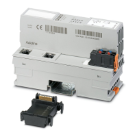
Details RS-232 and TTY interface connectors (SUB-D and COMBICON).
Instructions for mounting and removing the module on DIN rails.
Importance and method of connecting the functional earth for shielding and transient protection.
Instructions for connecting shielded cables and grounding the shielding.
Lists pin assignments for RS-232 interface connections on the module.
Describes how to wire the PSM module to peripheral devices using RS-232.
Explains the function of the diagnostic LEDs for RS-232 data transmission.
Details how to use switch S1 for DTE/DCE configuration.
Explains how to configure CTS/RTS control lines and internal bridging.
Lists pin assignments for TTY interface connections on the module.
Describes the active, semi-active, and passive operating modes for the TTY interface.
| Product Series | PSM |
|---|---|
| Category | Control Unit |
| Input Voltage | 24 V DC |
| Number of Outputs | 1 |
| Degree of Protection | IP20 |
| Output Voltage | 24 V DC |
| Nominal Output Voltage | 24 V DC |
| Connection Method | Screw connection |
| Operating Temperature | -25°C to +70°C |
| Storage Temperature | -40°C to 85°C |
| Mounting | DIN rail mount |
| Width | 22.5 mm |
| Weight | 150 g |