Do you have a question about the Phoenix Contact QUINT4-PS/1AC/48DC/20 and is the answer not in the manual?
Provides a concise overview of the product's technical specifications.
Lists available accessories for mounting and enhancing the power supply functionality.
Details the electrical input characteristics and ranges for the power supply.
Specifies typical current consumption values under various conditions.
Describes the power supply's ability to maintain output during short power interruptions.
Specifies connection methods and parameters for the output terminals.
Details the function of the LED indicators for output power status.
Provides connection parameters for signal wiring using push-in technology.
Presents Mean Time Between Failures (MTBF) data for assessing reliability.
Estimates the expected service life based on capacitor performance.
Details environmental operating conditions, including temperature and humidity.
Describes the power supply's resistance to shock impacts.
Specifies the degree of pollution the device is designed to withstand.
Defines the climatic conditions the device is rated for.
Indicates the overvoltage category according to safety standards.
Lists relevant safety and electrical standards the product complies with.
Details electromagnetic compatibility requirements for power plant environments.
Lists the product's certifications and approvals from various bodies.
Covers noise emission and immunity standards for various environments.
Details test levels and criteria for electrostatic discharge immunity.
Specifies test levels and criteria for immunity to electromagnetic HF fields.
Details test levels and criteria for immunity to fast transient bursts.
Details test levels and criteria for immunity to surge voltage loads.
Specifies test levels and criteria for immunity to conducted interference.
Details test levels and criteria for immunity to power frequency magnetic fields.
Specifies test levels and criteria for immunity to voltage dips.
Details test levels and criteria for immunity to pulse-shaped magnetic fields.
Specifies test levels and criteria for immunity to damped oscillating magnetic fields.
Details test levels and criteria for immunity to attenuated sinusoidal oscillations.
Specifies test levels and criteria for immunity to asymmetrical conducted disturbances.
Details test levels and criteria for immunity to attenuated oscillating waves.
Explains the safety symbols and warning labels used throughout the document.
Provides essential warnings and precautions for safe installation and operation.
Explains the purpose and process of high-voltage dielectric testing for safety.
Details the high-voltage testing performed during the manufacturing phase.
Clarifies the customer's role regarding high-voltage dielectric testing.
Provides guidelines for performing high-voltage tests on the control cabinet or power supply.
Describes how to disconnect the gas discharge tube for specific testing procedures.
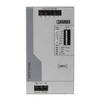
Identifies and describes the key operating and indication elements on the power supply.
Provides the physical dimensions of the power supply unit in millimeters.
Illustrates device dimensions and required clearance zones for proper installation.
Presents a functional block diagram of the power supply's internal components.
Details the step-by-step procedure for mounting the power supply unit.
Explains how to safely remove the power supply unit from its mounting.
Describes how to attach or modify the DIN rail adapter for mounting.
Details the mounting of the universal DIN rail adapter on the device's left side.
Explains how to attach the universal wall adapter for alternative mounting.
Details the mounting procedure for the UWA 182/52 universal wall adapter.
Details the mounting procedure for the UWA 130 2-piece universal wall adapter.
Provides instructions on securing the connection wiring using cable binders.
Details the input connection terminal blocks and network types.
Covers primary side protection requirements and line protection.
Explains how to adjust the output voltage using front panel controls.
Describes the secondary side's short-circuit and no-load protection features.
Shows pin assignment and protection for AC supply voltage connections.
Shows pin assignment and protection for DC supply voltage connections.
Categorizes applications based on output characteristics for customization.
Summarizes the key benefits associated with each output characteristic.
Lists and describes different output characteristic curves like U/I Advanced and Smart HICCUP.
Details the U/I Advanced output characteristic curve optimized for various applications.
Details the Smart HICCUP mode for managing thermal load and overloads.
Explains the FUSE MODE for permanent shutdown on overload and restart options.
Outlines the hardware and software requirements for configuring via PC.
Describes the general procedure for configuring the power supply, including SLEEP MODE.
Explains how to configure the power supply using a mobile device and NFC interface.
Details how to order pre-configured power supplies for specific applications.
Describes the static boost feature for sustained load supply up to 112% of nominal current.
Explains the dynamic boost feature for temporary high loads up to 200% for 5 seconds.
Provides recovery time tables for dynamic boost at 40°C ambient temperature.
Provides recovery time tables for dynamic boost at 60°C ambient temperature.
Illustrates how to determine the recovery time using provided tables and an example.
Explains how SFB Technology reliably trips circuit breakers quickly.
Describes how SFB Technology works with fuses for selective tripping.
Outlines framework conditions for SFB configuration, including cable length.
Determines maximum distances for reliable tripping of circuit breakers and fuses.
Provides maximum distances for Phoenix Contact CB TM1 SFB circuit breakers.
Lists maximum distances for Siemens 5SY and ABB S200 circuit breakers with various conductor cross sections.
Provides maximum distances for Cooper Bussmann GMA and GMC fuses.
Identifies and describes the location and function of all signaling elements.
Provides a key for the signaling elements and their functions.
Describes the floating signal contact's function and switching behavior.
Explains the function of digital signal outputs for monitoring and control.
Details the use of the analog signal output for continuous workload monitoring.
Details customizable signal options for monitoring system states.
Shows the default signal assignments for various monitored parameters.
Explains how different parameters trigger signal state changes.
Describes signaling for output voltage status and threshold detection.
Explains signaling for output current exceeding set thresholds.
Details signaling for output power exceeding set thresholds.
Describes signaling for exceeding preset operating hours for maintenance planning.
Provides early warning of high temperatures before derating occurs.
Indicates when the output voltage limitation for surge protection is activated.
Signals input voltage status and potential mains failure in advance.
Explains using the digital remote input for switching the power supply on/off.
Details the function of the four LED indicators showing device status.
Shows the standard signal assignments for the U/I Advanced characteristic curve.
Details the standard signal assignments for the Smart HICCUP characteristic curve.
Shows the standard signal assignments for the FUSE MODE characteristic curve.
Describes the LED and signal states when the power supply is in SLEEP MODE.
Details surge protection requirements for signal wiring in various environments.
Details surge protection requirements for power plant signal applications.
Specifies surge protection for signal wiring in railway applications.
Outlines surge protection for safety-related systems and functional safety.
Explains how to connect two power supplies in series to double the output voltage.
Describes connecting multiple power supplies in parallel for increased power or redundancy.
Explains how to connect power supplies in parallel for redundant power supply.
Details connecting power supplies in parallel to increase total output current.
Explains power derating due to ambient temperature exceeding nominal limits.
Describes derating based on input voltage variations and ambient temperature.
Details how installation height affects performance due to air pressure and cooling.
Explains how mounting orientation affects output power and requires derating.
Shows output power derating for the normal horizontal mounting position.
Illustrates derating curves for a 90° Z-axis rotated mounting position.
Shows output power derating for a 180° Z-axis rotated mounting position.
Illustrates derating curves for a 270° Z-axis rotated mounting position.
Shows output power derating for a 90° X-axis rotated mounting position.
Illustrates derating curves for a 270° X-axis rotated mounting position.
| Brand | Phoenix Contact |
|---|---|
| Model | QUINT4-PS/1AC/48DC/20 |
| Category | Power Supply |
| Language | English |