VALUELINE IPC
2643_en_K PHOENIX CONTACT 11
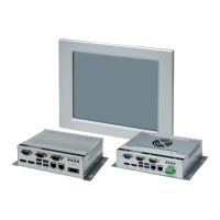
Figure 8 PCI slot 0 card installation
c) Attach the PCI card, 1, to the bracket frame, 2, and
secure it with the retaining screw and washer
previously removed.
d) Position the PCI card and frame assembly so the
frame assembly rests on top of the vibration
reduction strip. Carefully push the card into the
connector, 3, ensuring the frame assembly aligns
with the mounting holes in the chassis and the card
is properly seated in the connector.
e) Secure the bracket frame to the chassis using the
two Phillips-head screws previously removed in
step a).
6. Re-install the top cover, and replace and tighten the
four screws previously removed.
7. Reconnect power to the VL IPC.
8. Start the VL IPC.
6Operations
6.1 Software license and activation
Use of the Microsoft
®
operating system is subject to the li-
censing limitations specified by the Microsoft Software Li-
cense. Phoenix Contact is not responsible and cannot be
held liable for proper use of the operating system or any
other software installed on the computer unless that soft-
ware is a product developed and manufactured by
Phoenix Contact.
To reduce software piracy and provide customers with qual-
ity service, Microsoft includes a product activation require-
ment on some software, including some operating systems.
Use of the software is limited to the first 30 days after first
launching the software unless the product activation pro-
cess is completed. A pop-up program prompts the user to
begin the process when the software is first started. If acti-
vation is not completed, the software repeats the product
activation pop-up on a pre-determined cycle. Once started,
message boxes lead the user through the process to obtain
proper product activation.
Additional details are included in the Microsoft Software Li-
cense and are also available at www.Microsoft.com
.
The Windows product key is on a sticker that is affixed to the
VL IPC.
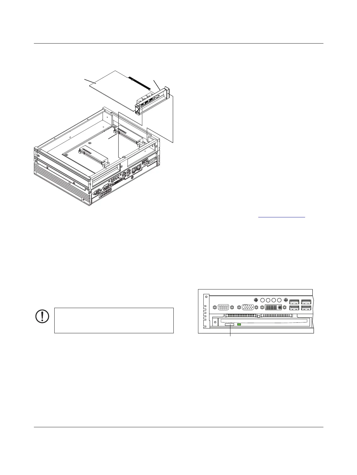
6.2 Accessing the optical drive
Use the optional CD-RW/DVD-RW to install programs or
backup control programs and data. To insert or remove a
CD/DVD, follow these steps:
1. Open the access door.
2. Press the eject button to remove an optical disk.
Figure 9 Optical drive eject button
3. Insert the CD/DVD in the proper orientation for the
drive. The recorded/recordable side should face down
or left.
4. Gently push the CD/DVD disk in the slot.
NOTE:
Tighten all screws on the VL IPC frame to no more
than 7 Nm.
4
876
1 3
2
9
5
X10 COM1 X9 VGA
X8 DVI D
ERROR RUN HDD PWR
X7 USB
X5 USB
X4 USBX6 USB
Optical drive
eject button
 Loading...