P
P
H
H
O
O
E
E
N
N
I
I
X
X
U
U
N
N
L
L
I
I
M
M
I
I
T
T
E
E
D
D
L
L
L
L
C
C
-
-
-
-
-
-
-
-
-
-
-
-
-
-
-
-
-
-
-
-
-
-
-
-
-
-
-
-
-
-
-
-
-
-
-
-
-
-
-
-
-
-
-
-
P
P
H
H
X
X
-
-
2
2
0
0
0
0
-
-
-
-
-
-
-
-
-
-
-
-
-
-
-
-
-
-
-
-
-
-
-
-
-
-
-
-
-
-
-
-
-
-
-
-
-
-
-
-
-
-
-
-
-
-
-
-
-
-
-
-
-
-
-
-
-
-
-
-
-
-
U
U
S
S
E
E
R
R
S
S
G
G
U
U
I
I
D
D
E
E
P
P
G
G
.
.2
TABLE OF CONTENTS
SYSTEM I.D. 3
EQUIPMENT WARRANTY 4
INTRODUCTION 5
SAFETY PRECAUTIONS AND WARNINGS 6-7
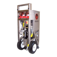
PHX-200 KEY COMPONENT IDENTIFICATION 8
CONTROL PANEL/WARNING LABEL 9
OPERATION INSTRUCTIONS
Connecting the Air Supply 10
Connecting the Blast Gun 11
Pre-Start Up Checks 12
Loading Dry Ice 13
Applying Air to Unit 14
Setting the Panel Controls 14
Arming/Disarming 15
Ready to Blast 15
Stop Blasting 16
Shut Down 17
PREVENTIVE MAINTENANCE
Daily Preventive Maintenance 18
Adding Oil 19
Main Filter Inspection and Replacement 20
Trigger Line Filter and Blast Air Pilot Filter 21
PERIODIC MAINTENANCE
Auger Drive Chain, Check/Adjust 22-23
Airlock 24-27
FACTORY SETTINGS 28-29
PHX-200 KEY POINTS 30-31
TROUBLESHOOTING 32-37
DRAWINGS
List of Drawings 37
Schematic & Reference 38-39
Tube Diagrams 40-43
Filter/Regulator Diagram 44
Air System Assembly 45
Control Panel Assembly 46-47
Control Shelf Assembly 48-49
E-Stop Assy 49
Regulator Assemblies 49
Vibrator Assembly 51
Airlock Assembly 52-53
Gun Assembly 55-56
SPECIFICATIONS 57
RECOMMENDED SPARE PARTS LIST
CUSTOMER SUPPORT 59