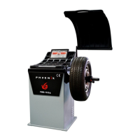
This document outlines the installation, operation, and maintenance of a Phoenix Auto Equipment wheel balancer, model PWB-1535A. It serves as a comprehensive guide for operators to ensure safe and efficient use of the machine.
The primary function of this device is to balance wheels, ensuring smooth operation and extended tire life. It is designed to identify and measure imbalances in a wheel assembly, allowing the operator to add corrective weights to achieve a balanced state. The balancer supports various modes, including standard dynamic, static, ALU1-3, ALUS, OPT, and motorcycle modes, catering to different wheel types and balancing requirements.
For safe operation, the manual emphasizes several key points. Operators must be properly trained and should avoid wearing loose clothing or jewelry that could become entangled with moving parts. Protective eye gear, such as safety glasses, goggles, or face shields, is mandatory. Sturdy leather work shoes with steel toes and oil-resistant soles are also recommended for general shop safety. A safety guard is provided and should always be used to prevent injuries. The wheel balancer is an electronic device and must be kept indoors in a dry environment, as exposure to water or extreme heat can cause damage not covered by warranty. It is crucial to use a power surge protector to safeguard the machine from electrical surges or storms, as it does not have a built-in one. The balancer should not be used beyond its specified measurement or weight range, as this could damage the machine and compromise the accuracy of the balance. Adherence to OSHA and local safety regulations is also required. All instructions and labels on the unit must be kept clean and visible.
The PWB-1535A model is designed for ease of use, particularly with its automatic gauge feature. In dynamic, static, and ALU modes, the balancer automatically detects the distance of the wheel from the machine and the rim diameter. The operator only needs to manually input the wheel width. This streamlines the balancing process compared to standard balancers that require all three parameters to be entered manually. For ALUS mode, four parameters are required, which are also largely automated by the gauge.
Installation of the wheel balancer involves several straightforward steps. First, the machine must be removed from its shipping crate and pallet. It should then be placed on a flat and stable floor. The safety hood needs to be installed, followed by the threaded rod for spinning the wheel, secured with a hex bolt. If the wheel balancer experiences shaking or movement during operation, it must be bolted to the ground to ensure proper function and accurate balancing. The electrical plug is preinstalled for North American 110-volt electrical sockets, and it should be plugged into a proper electrical outlet. Direct hardwiring to the electrical source is not recommended. As mentioned, a power surge protector is essential to prevent damage.
The control panel features various indicators and keys for different functions. Display windows show inside and outside unbalance points, as well as middle static unbalance. Indicators for sticking and clamping weight positions are also present. Keys are provided for dynamic, static, ALU, ALUS, OPT, split/hidden weight, mm/inch, and motorcycle modes. There are also keys for wheel parameters input, up, down, enter, measurement unit, start, fine measurement, and stop functions.
System settings allow the user to customize the balancer's operation. These settings can be accessed by holding down the "ENTER" button. Operators can navigate through settings using the UP and DOWN keys. Settings include guard control (to enable or disable spinning with the hood up), standardization display (setting the weight display multiple, e.g., 1g or 5g), least unbalance value (setting a threshold below which unbalance is displayed as 0), buzzer switch (on/off), width input unit (grams or ounces), diameter input unit (grams or ounces), and unbalance unit of measurement (grams or ounces). Changes are saved by pressing the WHEEL PARAMETERS INPUT AND SHIFT KEY, or discarded by pressing the STOP key.
Calibration is a critical maintenance step that must be performed before balancing a wheel. It is also necessary if the balancer is moved, unplugged, or loses power. To calibrate, a 15 or 14-inch steel rim with a tire is required. The process involves entering wheel parameters, then holding the FINE button for 3 seconds. The operator then closes the safety hood and spins the wheel. After the wheel stops, a 100-gram or 3.5-ounce weight is placed at the 12 o'clock position on the outside of the rim, and the wheel is spun again. After removing the weight, the tire is rotated until all lights in the INSIDE UNBALANCE POINT are on. Another 100-gram or 3.5-ounce weight is then placed at the 12 o'clock position on the inside of the rim, and the wheel is spun one last time. Successful calibration is indicated by a specific screen display, after which the machine returns to the initial balancing screen. If the calibration fails (e.g., due to not adding weights), an error screen will appear, and the process must be repeated.
The standard dynamic mode is used for balancing steel wheels by placing clip-on weights on both the inside and outside of the rim. It is not intended for aluminum wheels or stick-on weights. The balancing process involves placing the wheel, entering parameters, spinning the wheel, rotating the tire to align with display lights, adding the calculated weight, and spinning again until both sides are balanced. The FINE button can be used in any mode to display the exact unbalance value, down to 1 gram or 0.10 ounce, even if the least unbalance value setting has rounded the display to zero.
Static mode functions similarly to dynamic mode but only balances the wheel by placing weight on the outside of the rim. ALU1-3 modes are designed for rims that do not accept clip-on weights on one or both sides, using stick-on weights instead. The STICKING AND CLAMPING WEIGHT POSITION INDICATOR on the display guides the placement of these weights. ALUS mode requires four parameters and is considered the most accurate for stick-on weights. OPT mode refers to tire manufacturing instructions for matching tires to the correct rim. Motorcycle mode requires a special adapter, sold separately, to mount motorcycle wheels for balancing, following the same 3-parameter input and balancing process as dynamic mode.
Troubleshooting guidance is provided for common errors. "CCC CCC" indicates that the measurement result is beyond the range, often due to incorrect calibration or a wheel that is too light or too heavy. "OFF OFF" occurs when the STOP button is pressed while the wheel is spinning. "Err 01" signifies that the guard was not closed or was raised during a spin attempt; this can be resolved by turning guard control off in system settings or ensuring the guard remains closed. "Err 02" points to a low rotating speed, suggesting issues with the drive belt, spin shaft, or motor, or that a heavier wheel is needed. "Err 03" indicates rotation in the wrong direction, relevant for 3-phase motors requiring adjustment of wires. "ERR CAL" means the machine is not calibrated, prompting the user to follow calibration steps. "ERS CAL" is a factory maintenance error, requiring contact with the manufacturer. If the machine continuously asks for more weight, it suggests improper calibration, incorrect parameter entry (parameters are not saved when the machine is turned off), or a defective weight sensor board. Electrical issues like tripping breakers or overheating/shutting down automatically point to defective transformers or power boards, requiring replacement or temperature checks. If the machine does not turn on, it suggests an error in electrical wiring, prompting checks of the on/off switch, wire connections, and electrical current.