17
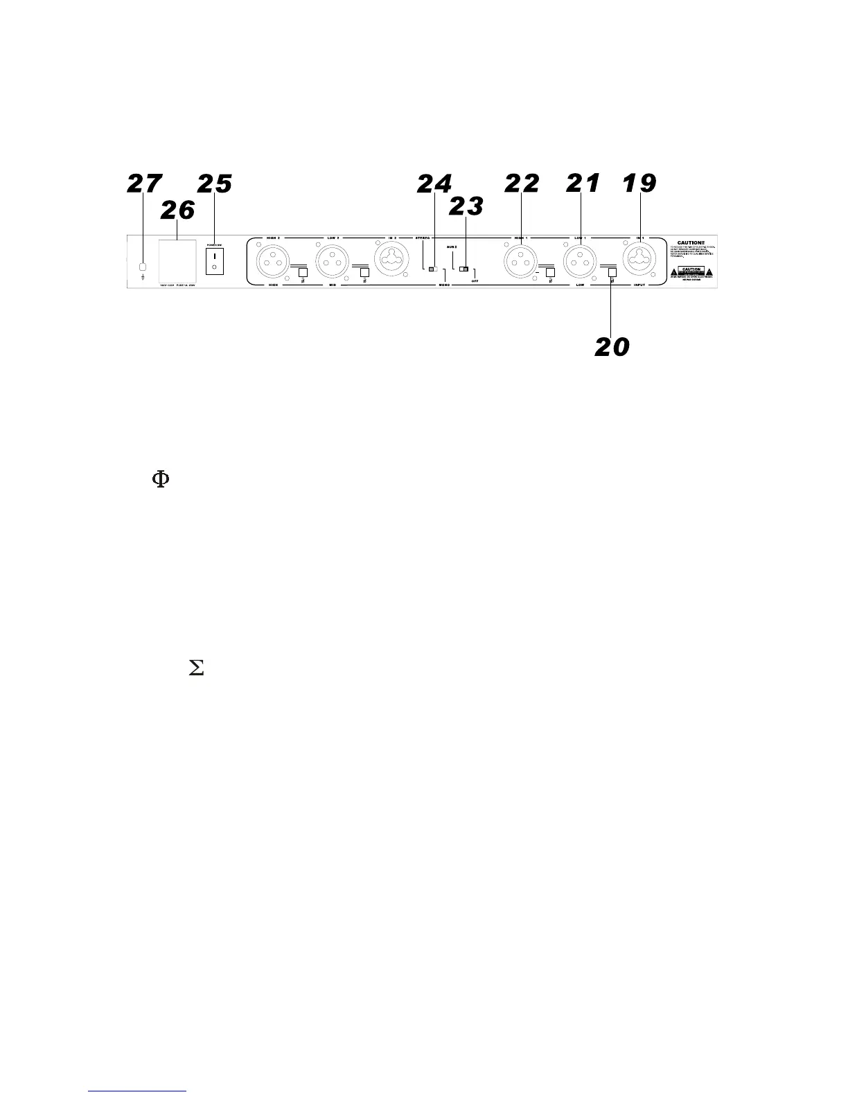
4.2 REAR PANEL
Just like the front panel, the text above the input/output sockets are STEREO mode and the text below the
sockets are MONO mode. They are clearly marked to minimize mistakes.
1919
1919
19. IN 1 / IN 2
The input sockets are standard XLR female type. Set in the signal to IN 1 in MONO mode. The IN 2 socket is
not effective in MONO mode.
2020
2020
20.
These are phase invert buttons, the phase will be inverted as soon as the button is pressed.
2121
2121
21. LOW 1 / LOW 2
These are the LOW outputs. In MONO mode, they become LOW and MID output.
2222
2222
22. HIGH 1 / HIGH 2
These are the HIGH outputs. In MONO mode, HIGH 1 is not in used. HIGH 2 is the HIGH output.
2323
2323
23. SUB
When set this switch to the left, the low portions of the 2 lows are summed. It will be disengaged automatically
when in MONO mode.
2424
2424
24. STEREO/MONO
Slide to left for STEREO 2-way mode, and slide to right for MONO 3-way mode.
2525
2525
25. POWER SW.
To turn the unit on and off. This switch is best located in the rear panel to avoid accidental tampered during
operation which endanger the whole speaker system.
2626
2626
26. POWER SOCKET
Standard IEC socket for power connection. Check the voltage before connection.
2727
2727
27. GROUND POINT
Chassis grounding point for properly grounding.