Installation
Manual piCOMPACT
®
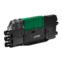
23 SMART IO-Link Ready 2 channel Page 15/24
Pin No. Name Description Note
1 Vsys Supply voltage, 24 VDC (V+)
2 GND Common, 0 VDC (V-)
3* V1
0 = Vacuum control
Digital input
Valve 1 control or C2
control functions
1 = Blow-Off control
2 =Disable Energy Saving (ES)
3 = Disable Automatic Blow-Off functions (ATBO or IBO)
4 = Disable Automatic Condition Monitoring (ACM)
5 = Process Data Out valid (PDO)
4* V2
0 = Vacuum control
Digital input
Valve 2 control or C2
control functions
1 = Blow-Off control
2 =Disable Energy Saving (ES)
3 = Disable Automatic Blow-Off functions (ATBO or IBO)
4 = Disable Automatic Condition Monitoring (ACM)
5 = Process Data Out valid (PDO)
5* S1**
0 = No function Digital output
Signal 1**
1 = Part Present vacuum level achieved (PP)
2 = Energy Saving vacuum level achieved (ES)
3 = Leakage Warning (LW)
4 = Blow-off Complete (BOC)
6* S2**
0 = No function
Digital output
Signal 2**
1 = Energy Saving vacuum level achieved (ES)
2 = Part Present vacuum level achieved (PP)
3 = Leakage Warning (LW)
4 = Blow-off Complete (BOC)
5 = Analog output, 1-5 VDC
7* C1 Invert Interpretation of pump I/O, connect pin 7 to pin 2 to
go from: PNP -> NPN or NPN -> PNP.
Control function also configurable in pump menu system.
8* C2
0 = No function
Digital input
Control 1
1 =Disable Energy Saving (ES)
2 = Disable Automatic Blow-Off functions (ATBO or IBO)
3 = Disable Automatic Condition Monitoring (ACM)
4 = Process Data Out valid (PDO)
*Different operating alternatives depending on your piCOMPACT® 23 SMART configuration.
**S1 and S2 can deliver 2x40mA simultaneously or 1x80mA one at a time.
Bold text = Preset value (S2 offers different presets depending on configuration)