SECTION 4 - PROGRAMMING GUIDE
Page 4.3
PXI/PXIe LVDT/RVDT/Resolver Simulator Module 41/43-670
pickering
Setting The Simulation Conguration
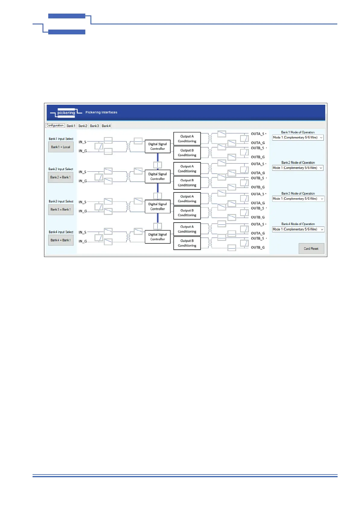
The fully populated 41/43-670 Simulator has 4 banks and consists of four inputs and eight outputs, which may
be set into several congurations to represent the desired hardware. This is illustrated by the Soft Front Panel’s
Conguration screen.
Each bank’s input may be congured independently into one of three states:
• Local – Inputs can have separate unique excitation signals applied to each bank
• Bank1 – Bank2, Bank3 and Bank4 can use the signal applied to Bank1
• Internal – No input is required and the reference is generated internally
Note: Input switches will be automatically selected for correct conguration, the SFP is programmed to allow only
Bank1 to share its input between other banks. This is for simplicity and not limited by the hardware.
Each of the bank’s A and B outputs can be congured for different modes of operation:
• Mode 1 – 5/6-Wire (2 complementary outputs)
• Mode 2 – 4-Wire (2 independently controllable outputs)
• Mode 3 – Resolver
A description of the modes of operation is given in Section 2
Note: Output switches will need to be closed as required to obtain an output, the SFP controls the switches as
required by the selected mode, but they are able to be separately controlled in software.
The input and output switches can be used to isolate and apply shorts to the bank’s inputs and outputs as required
for fault simulation. The switch contacts are all rated 0.5A Switching 1.2A carry current - 10Watts.
Figure 4.2 - Soft Front Panel Conguration Screen Used to Set the
LVDT Simulator Module’s Modes of Operation