Page 4.6
SECTION 4 - PROGRAMMING GUIDE
PXI/PXIe LVDT/RVDT/Resolver Simulator Module 41/43-670
pickering
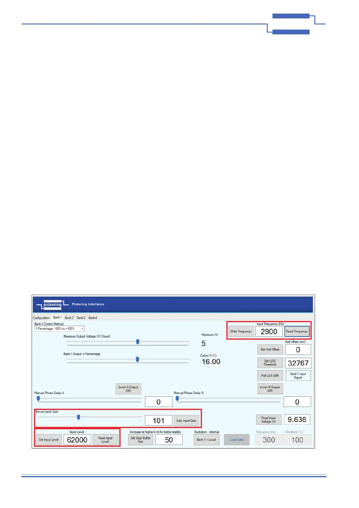
Write Frequency & Set Input Level
‘Write Frequency’ can be used to x the applied excitation frequency calculation, changes or even small variations
in the excitation frequency will be ignored. Write 0 to measure the excitation frequency at the input.
‘Set Input Level’ can be written to ignore the actual reading of the input level, this can be used to x the settings
before an excitation signal has been applied, this will in effect disable the Loss of Signal functionality, reading the
input level will return the value set, not the actual input level. Write 0 to measure the amplitude at the input.
Using both these functions together can force the card to assume a signal is present before its applied.
In order to set VSUM without an input signal:
Pre-setting an Input Level is an advanced feature to allow VSUM to be set before a signal is applied, but rst you
must obtain the correct input level value by applying a real signal. Please follow the sequence as detailed below:
• Congure the bank setting of the channel and apply the desired excitation signal.
• In the Bank tab, click on ‘Auto Input Gain’ and record the value (1 - 255).
• Click ‘Read Input Level’ and record the value (32768 - 65535).
• Click ‘Read Frequency’ and record the value.
• This data set will be associated to the current channel and excitation signal properties.
• When using the simulator, set the manual input gain with the number recorded previously and do the same
with input level and frequency parameters, remembering to click on the set buttons after typing the recorded
values in the respective boxes.
• At this point, VSUM can be set with no excitation signal connected (the simulator will use the values input by
the user instead of measuring them).
• After setting VSUM, writing 0 to the frequency and input level registers will make the module automatically
detect them as soon as the excitation signal is connected.
(Please be aware that if using xed amplitude or frequency this will override the input signal which may
result in an unexpected output, as the real parameters will not be sensed by the module)
Loss of signal (LOS) feature - if a loss of input signal is detected the internal adjustments will be suspended
automatically, when the signal is reapplied the output will be regenerated using previous calibration allowing the
signal to recover.
Figure 4.5 - Write Frequency and Set Input Level Features