SECTION 4 - PROGRAMMING GUIDE
Page 4.9
PXI/PXIe LVDT/RVDT/Resolver Simulator Module 41/43-670
pickering
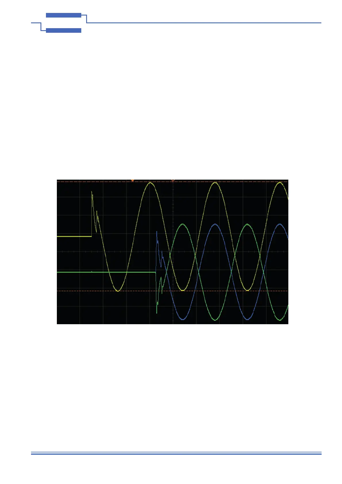
Loss of Signal Threshold
The LOS threshold can be used to set the minimum valid amplitude level of the applied input signal. In the event of
loss of signal the frequency calculation is frozen. This allows the output to return immediately (within one cycle) in
phase as soon as the same excitation frequency is reapplied, this saves the module retaking multiple samples of
the input to calculate frequency and applying the correction. During the LOS event the frequency and input level will
return the last valid measurements.
If this feature is not used, a non-existent input signal will be sampled and an unknown frequency calculated so when
excitation is reapplied it could take the buffer’s size of samples to re-stabilize. To the give buffer time, the same
calculation will be required to re-stabilise based on buffer size and excitation frequency.
The LOS threshold is set to 32768 as default which is also the maximum, range 0-32768
Dropping below this threshold means the outputs will still be generated but correction will be applied based on the
last valid frequency and amplitude and the last Vsum function will continue to be used.
Figure 4.8 - Generation of Output Signals After Loss of Excitation Input Signal
Using Loss of Signal Threshold Feature