Page 4.14
SECTION 4 - PROGRAMMING GUIDE
PXI/PXIe LVDT/RVDT/Resolver Simulator Module 41/43-670
pickering
Phase Offset Alignment
Interwinding and stray capacitance effects on the output phase angle can be replicated buy adjusting the output
phase lag value. It can be adjusted from the zero ‘in phase’ reference position in 555ns increments, both outputs A
and B can be adjusted independently.
The number of increments of adjustment is dependent on the excitation frequency:
1/300Hz = 3.33ms per cycle /555ns = 6006 per cycle at 300Hz
1/1kHz = 1.00ms per cycle /555ns = 1801 per cycle at 1kHz
1/3kHz = 3.33µs per cycle /555ns = 600.6 per cycle at 3kHz
The adjustment is from 0 (in phase) to 6499. If a leading phase simulation is required, it can be done with reference
to the next cycle.
At 1kHz:
1801/360° = 0.2° per increment
0 is in phase with second excitation cycle
1801 is in phase with third excitation cycle
1796 would give a 1° leading phase relative to third excitation cycle (5x0.2=1°)
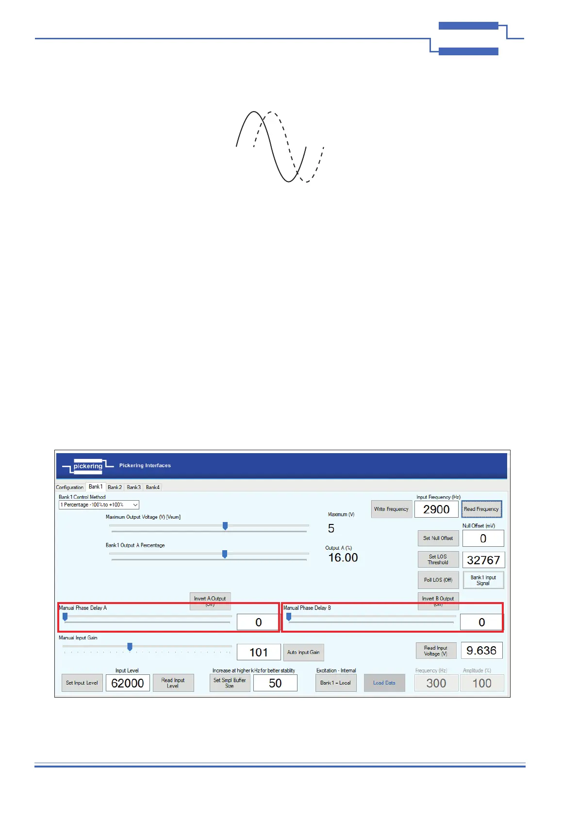
Figure 4.14 - Manual Phase Delay Feature for A and B Outputs