SECTION 4 - PROGRAMMING GUIDE
Page 4.15
PXI/PXIe LVDT/RVDT/Resolver Simulator Module 41/43-670
pickering
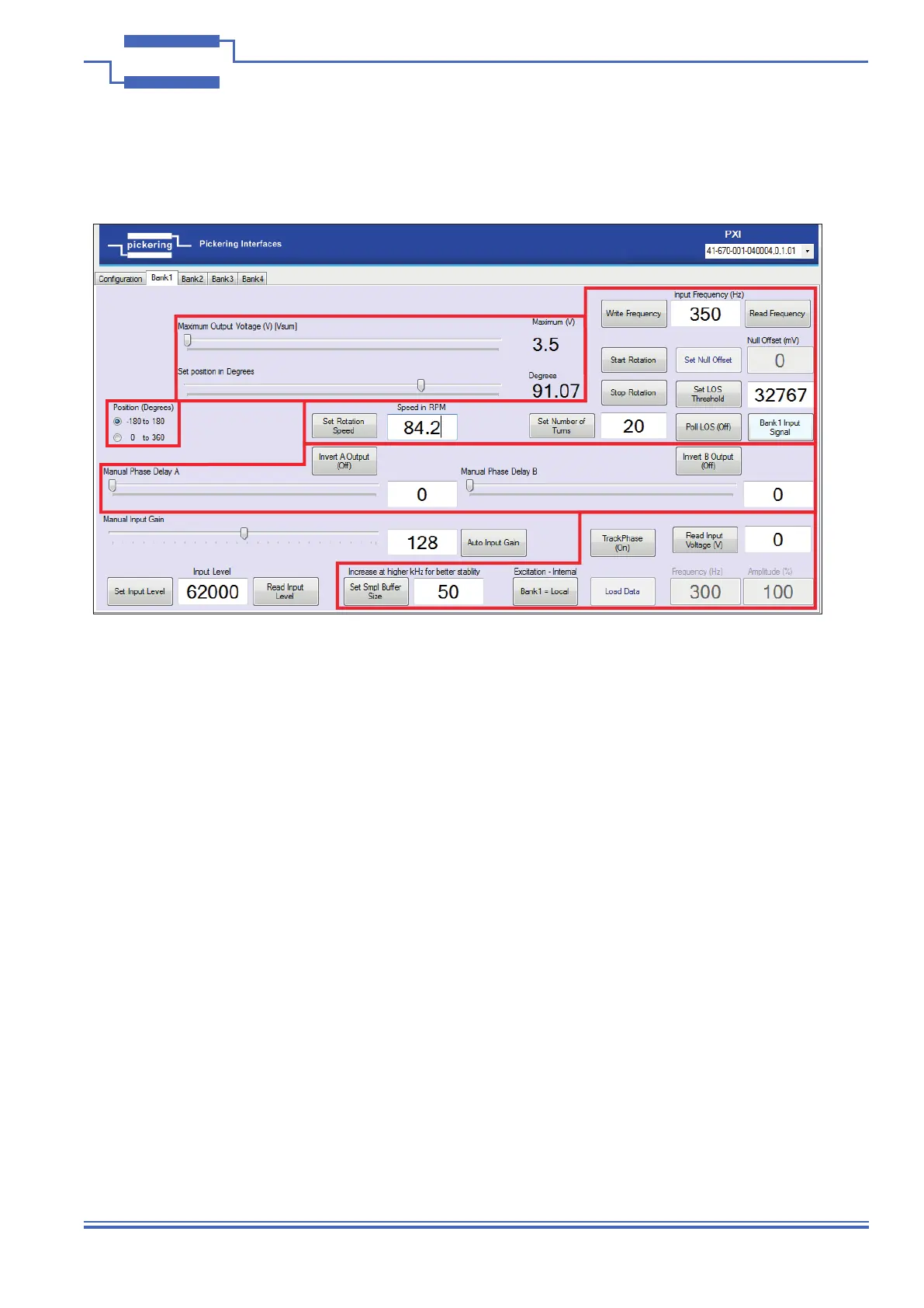
Resolver Mode
Selecting ‘Mode 3’ as the mode of operation on the conguration screen sets the simulator module into resolver
mode. The bank controls for this mode are outlined below:
Zone 1 - Shows the method of operation for the “Set Position in Degrees” control shown in Zone 2. It will set the
scale to -180 to 180 degrees, or to 0 to 360 degrees - whatever is suitable for you application.
Zone 2 - This shows the main method of controlling the output of the bank:
• The top slider “Maximum Output Voltage (V) [VSUM]” controls the maximum output voltage.
• The second slider “Set Position in Degrees” sets the rotation within a range of either -180 to 180 degrees or 0
to 360 degrees as selected in the Zone 1 option.
• Note; if you double click on the rst slider it will reset the “Set Position in Degrees” slider below it.
Zone 3 - These are some of the auxiliary functions available for controlling the bank, these enable the manipulation
of Rotational speeds, iterations, Loss of Signal (LOS) and Frequency Read / Write functionality.
• “Write Frequency” - Sets the frequency value from the adjacent text box.
• “Read Frequency” - Reads the current frequency value and sets it in the adjacent text box.
• “Null Offset” - Functionality is disabled in the Resolver mode, hence it is greyed out.
• “Set LOS Threshold” - This button reads the value from the adjacent text box and uses it as the threshold
value used for Loss of Signal (LOS) detection.
• “Poll LOS (Off)” - This button will toggle the LOS functionality on or off. The adjacent box; “Bank 1 Input
Signal” will change colour to green when in operation and change to red when the LOS threshold has been
exceeded.
Figure 4.15 - Resolver Mode - Bank Controls
Zone 1
Zone 2
Zone 3
Zone
4
Zone
5