Do you have a question about the Pioneer A-A6-J and is the answer not in the manual?
| Impedance | 4 Ω |
|---|---|
| Frequency range | 20 - 20000 Hz |
| RMS rated power | 120 W |
| Audio output channels | 2.1 channels |
| Signal-to-Noise Ratio (SNR) | 103 dB |
| Total Harmonic Distortion (THD) | 0.2 % |
| Output power | 60 W |
| Dimensions (WxDxH) | 420 x 359 x 100 mm |
| Power requirements | 220 — 230 V, 50/60 Hz |
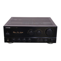
| Product color | Gray |
| Power consumption (standby) | 0.6 W |
| Power consumption (typical) | 170 W |
| Weight | 10000 g |
|---|
Covers warnings, notices for Canadian models, and general safety remarks.
Details essential safety checks like leakage current and product safety.
CAUTIONary notes on replacing and handling lithium batteries.
Emphasizes conforming to regulations and using specified parts for safe repairs.
Procedures for ensuring original product performance and characteristic confirmation.
Guidance on using specified lubricants, adhesives, and replacement parts.
Proper cleaning methods for optical pickups, heads, lenses, and mirrors.
Setting shipping mode or installing screws to prevent transit damage.
Details continuous power output, THD, and total harmonic distortion for models.
Covers input sensitivity, impedance, frequency response, and overload levels.
Includes power requirements, consumption, weight, and dimensions for models.
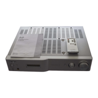
Lists furnished parts like remote control, power cable, and warranty card.
Exploded view and parts list for the A-A9 model's packaging.
Exploded view and parts list for the A-A9 model's exterior components.
Exploded view and parts list for the A-A6 model's packaging.
Exploded view and parts list for the A-A6 model's exterior components.
High-level block diagram illustrating the main functional units of the amplifier.
Illustrates the interconnections between various assemblies and components.
Circuit diagrams for Function, Headphone, Front, Motor VR, Remocon, Station, Power LED, VR assemblies.
Circuit diagram for the XM-Ready/USB interface.
Circuit diagrams for L-channel and R-channel amplifier, protection, and speaker boards.
Circuit diagrams for regulator IC and power supply assemblies.
Explains PCB diagram notation, symbols for components, and viewing points.
PCB connection layout for Sub-Trans, Power Switch, Station, Motor VR, XM-Ready/USB assemblies.
PCB connection layout for Function, Headphone, Front, Remote, Power LED, VR, L-Ch Amp/Prot, R-Ch Amp/Prot.
PCB connection layout for Regulator IC and Power Supply assemblies.
Compares construction differences for common assemblies between models.
Lists the parts for the A-A9 model's main PCB assemblies.
Lists the parts for the A-A6 model's main PCB assemblies.
Lists semiconductor, switch, and capacitor parts for the A-A9J model.
Lists semiconductor, capacitor, resistor, and other parts for the A-A6J model.
Procedure for adjusting idle current using VR702 and VR703.
Procedure for adjusting DC offset using VR701 and VR704.
Provides solutions for common issues like blown fuses, no display, or MICOM failure.
Explains protective operation modes and safe power amplifier capacitor discharge.
Illustrates the placement of PCBs when viewed from the top.
Illustrates the placement of PCBs when viewed from the front.
Step-by-step guide to remove the top cover and Function Assembly for A-A6 model.
Step-by-step guide to remove the top cover and Function Assembly for A-A9 model.
Instructions for removing the front panel assembly.
Details the pin arrangement and function for the main microcomputer IC102.
Visual representation of the microprocessor's internal structure and peripherals.
Lists the function of each pin on the main microprocessor.
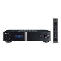
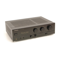
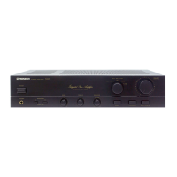
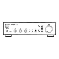
Identifies and explains the functions of front panel controls and displays.
Explains the functions of the remote control buttons.
Describes the meaning of different indicators on the front panel display.