40
1
234
12
34
F
E
D
C
B
A
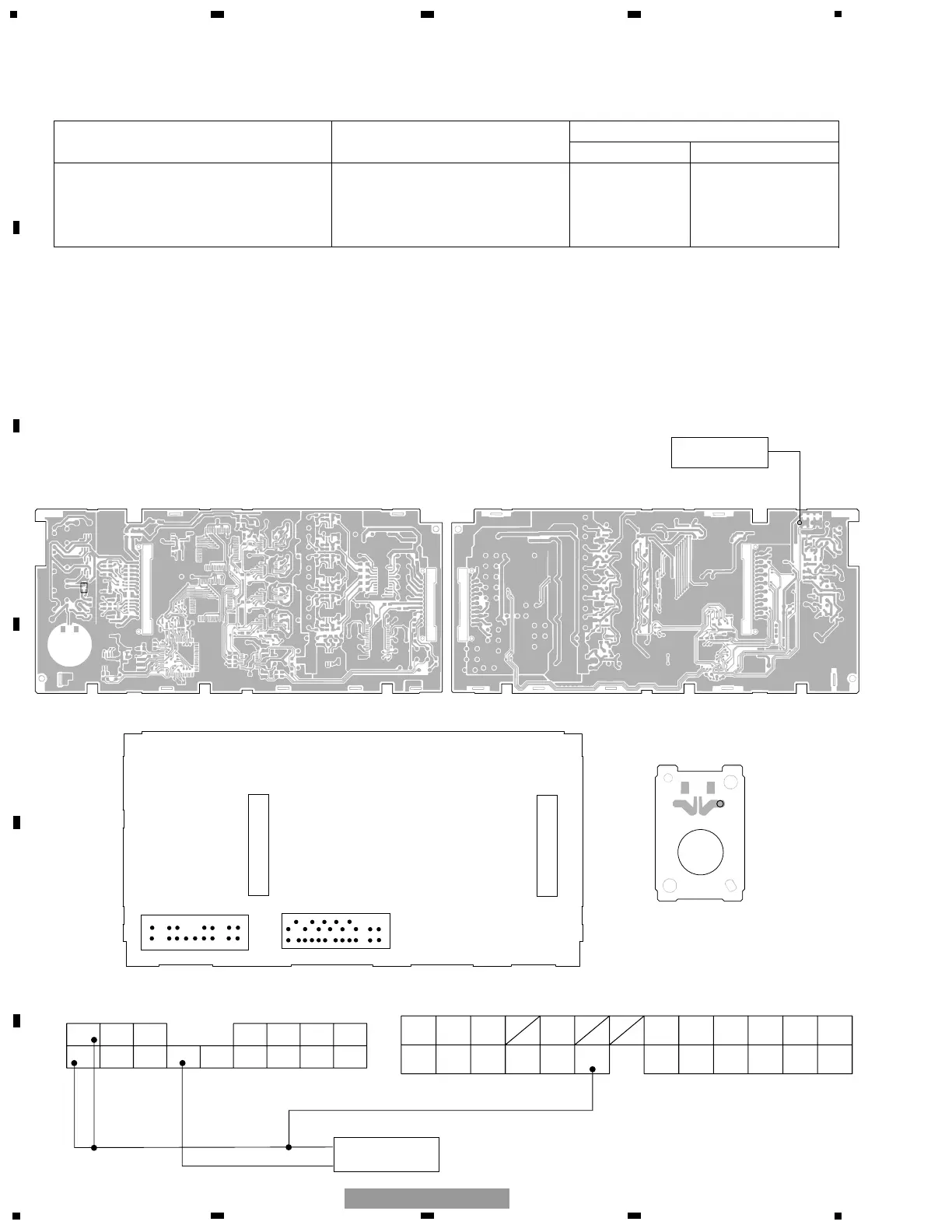
GM-8027ZT/WL
Preset conditions
1. Set VR401 around the center of the adjustable range.
Input Output Adjustment
(MIC) (Pin 74 : test point "ASL1") Adj.point Spec.
By using the jig(CAN-906,CAN-912), Observe the output at VR401 314±30mV
apply a sine wave of 100dBSPL ALS1 on a audio analyzer
voltage directly to the MIC terminal. (Corresponding to analog
(Close up as much as possible.) meter 7Hz).
To connect the Amp unit and the DSP unit, use Jig GGD1153 and GGD1245.
Caution:
1) Before starting measurement, be sure to perform the initial check for the ASL adjustment jig. (The sound pressure
level should be 100dBSPL at the sound emission section.)
2) Note that it may take 20 seconds or more to obtain waveforms, in some cases. Do not switch off the jig soon after
starting measurement.
Conditions:
1) This adjustment is sensitive to external shocks or wind. During adjustment, keep away the product and jig from
them.
 Loading...