45
5
6
7
8
F
E
D
C
B
A
5
6
7
8
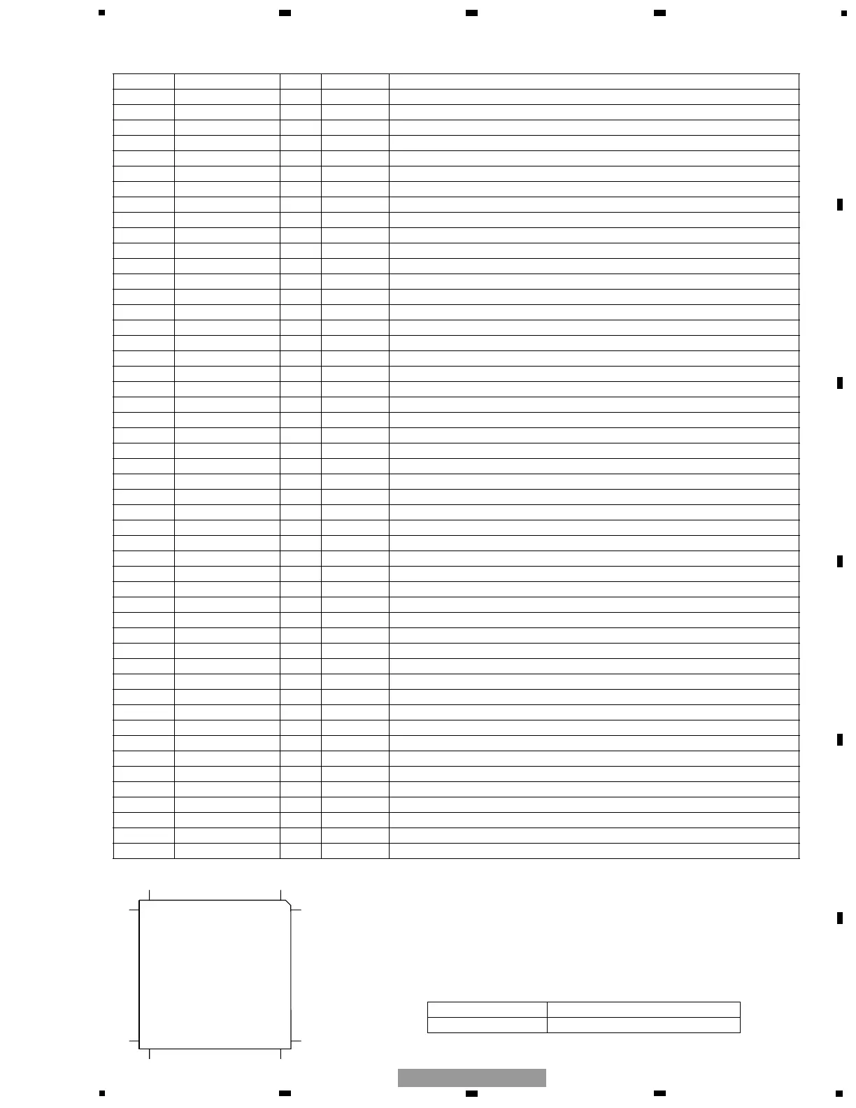
GM-8027ZT/WL
- Pin Functions (PD5726A, PD5792A)
Pin No. Pin Name I/O Format Function and Operation
1 MUTE O C Mute output
2 VCS2 O C SN761029 strobe output
3 VCS1 O C PM0017AM strobe output
4 VDT O C Data output for electronic volume
5 VCK O C Clock output for electronic volume
6 CVNSS Connect to VSS
7 MODEL0 I R handle /L handle select input
8 NC Not used
9 RESET I Reset input
10 XOUT O Crystal oscillating element connection pin
11 VSS GND
12 XIN I Crystal oscillating element connection pin
13 VCC 5V
14 NMI Connect to VCC
15 SPEED I Speed sensor pulse input
16 BSENS I Back up power sense input
17 ASENS I ACC power sense input
18 AVCINT I AVC-LAN data input
19 NC Not used
20 AVCPW O C AVC-LAN driver power supply output
21 PEE O C Beep tone output
22 AVCIN I AVC-LAN data input
23 AVCOUT O C AVC-LAN data output
24 DSPOUT O C DSPI/F serial data output
25 DSPIN I DSPI/F serial data input
26 DSPCK O C DSPI/F serial clock output
27 TESTIN I Test program start input
28 TSOUT O C Test serial data output
29 TSIN I Test serial data input
30 TSCK I Test serial clock input
31 SMUTEIN I System mute input
32-62 NC Not used
63 THROU I LOW fixed terminal
64 CALIB O C Power IC control output
65 PWSENS I Power IC heat sense input
66 SYSPW1 O C System power output
67 DSPRST O C DSP hard reset output
68 DSPERR I DSP error detect input
69 DSPCS2 O C TC9332F chip select 2
70 DSPCS1 O C TC9332F chip select 1
71 DSPACK I DSP-IC ACK input
72 DSPCD O DSP command/data output
73 DPD O C AD/DAC calibration output
74 ASLIN1 I Difference of noise and signal input 1
75 AVSS VSS
76 ASLIN2 I Difference of noise and signal input 2
77 VREF I A/D converter reference voltage input
78 AVCC VCC
79 NAVMUTE I Navigation mute input
80 DSPMUTE O C DSP mute output
 Loading...