Do you have a question about the Pioneer AVIC-U310BT and is the answer not in the manual?
General safety guidelines for servicing and operation, including laser safety and precautions.
Warning regarding potential chemical hazards as per California law.
General safety compliance and safe servicing environment.
Key points for adjustments, cleaning, lubrication, and shipping.
General guidelines for product servicing and IC handling.
Guidelines for using lead-free solder and proper soldering techniques.
Technical specifications for UC, EU5, and AU models, covering system, audio, and display details.
Information on supported disc and content formats.
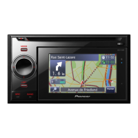
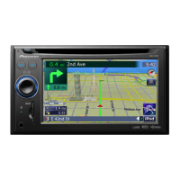
Identification and description of front panel controls and features.
Diagram illustrating system component connections.
Procedures to confirm product quality after repair.
Diagrams showing the physical location of main PCBs within the unit.
List of necessary jigs and prescribed cleaning tools for servicing.
System-level connection overview showing major components and interfaces.
Detailed block diagrams of the unit's circuitry, including PCB, power supply, and tuner units.
Flowchart showing the normal power-on operation sequence.
Flowcharts to diagnose issues with PND, Main Unit, GPS IF, and GPS antenna.
Table listing error codes, their display, and potential causes.
Descriptions of functions for various unit connectors and their pin assignments.
Instructions and list of test items for the Test Mode function.
Flowchart and key for operating the CD mechanism test mode.
Instructions for using TestDisc1 for various functional checks.
Steps for performing a restoration operation using TestDisc2.
Steps for removing the case, grille, CD mechanism, GPS IF unit, and main unit.
Steps for removing knob unit, grille PCB, button unit, battery, front cover, NAVI unit, and LCD panel.
Procedures for handling and disassembling the CD mechanism unit, including frames and core parts.
Cautions and steps for adjusting the CD mechanism.
Procedure to check and adjust the grating angle after pickup unit replacement.
Steps for calibrating the touch panel.
Exploded view and parts list for product packing.
Exploded view of external components (Part 1).
Exploded view of external components (Part 2).
Exploded view of the CD mechanism module components.
Detailed parts list for the CD mechanism module.
Schematic diagram for the main PCB.
Schematic diagram for the key PCB.
Schematic diagram for the CD mechanism module.
Examples of waveforms for CD core unit signals.
Diagram showing connections on the Main PCB.
Connection diagram for the Key PCB.
Connection diagram for the CD Core Unit.
List of miscellaneous parts including ICs, transistors, switches, diodes, and units.
List of resistors and diodes used in the circuit.
List of capacitors used in the circuit.
Continuation of the resistor list.
Continuation of the capacitor list.
Final part of the resistor list.
| Brand | Pioneer |
|---|---|
| Model | AVIC-U310BT |
| Category | Car Receiver |
| Language | English |