Do you have a question about the Pioneer CT-W606DR - Dual Cassette Deck and is the answer not in the manual?
| Tape Speed | 4.76 cm/s |
|---|---|
| Tape Type | Normal, Chrome, Metal |
| Signal-to-Noise Ratio (Normal) | 58dB |
| Signal-to-Noise Ratio (Chrome) | 58dB |
| Total Harmonic Distortion | 1.0% |
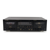
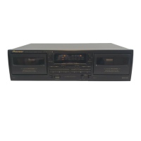
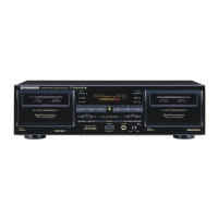
| Type | Dual Cassette Deck |
| Playback System | 2-channel stereo |
| Motor | DC servo |
| Output | 0.5V (line) |
| Inputs | Line In |
| Outputs | Line Out |
| Dimensions | 420 x 125 x 284 mm |
| Power Supply | AC 50/60 Hz |
General safety guidelines and warnings for technicians, including leakage current checks.
Details packaging contents and general parts list with diagrams.
Compares part numbers across different models for consistency.
Shows interconnections between major circuit blocks and units.
PCB connection layout for major components like main, motor, and eject units.
Explains how to interpret parts lists and resistor codes.
Lists all major PCB assemblies and their part numbers.
Compares PCB assemblies across different models.
Procedures for adjusting mechanical aspects of the deck.
Procedures for electrical calibration of the unit.
Aligning the playback head for optimal signal.
Setting the correct playback signal output level.
Calibrating the bias oscillator for recording.
General parts and component information.
Details display pinouts and wiring.
Explains display grid layout and anode wiring.
Procedures for initiating and stopping test modes.
How to navigate different test modes.
Lists the available main test modes.
Detailed steps for mechanism operation testing.
Explains error codes, their meanings, and causes.
Procedure for clearing recorded error codes.
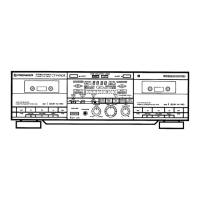
Description of front panel controls and indicators.
Details specific controls and displays for Deck I.
Details specific controls and displays for Deck II.
Describes shared controls like Power, Mode, and special function buttons.
Details on heads, motors, wow/flutter, and frequency response.
Technical audio performance metrics.
Electrical input and output characteristics.
Details on power, dimensions, and weight.
Lists prominent features and functions of the device.
Lists items supplied with the product.