DJM-500
NO, Pi
Name I/O
Function
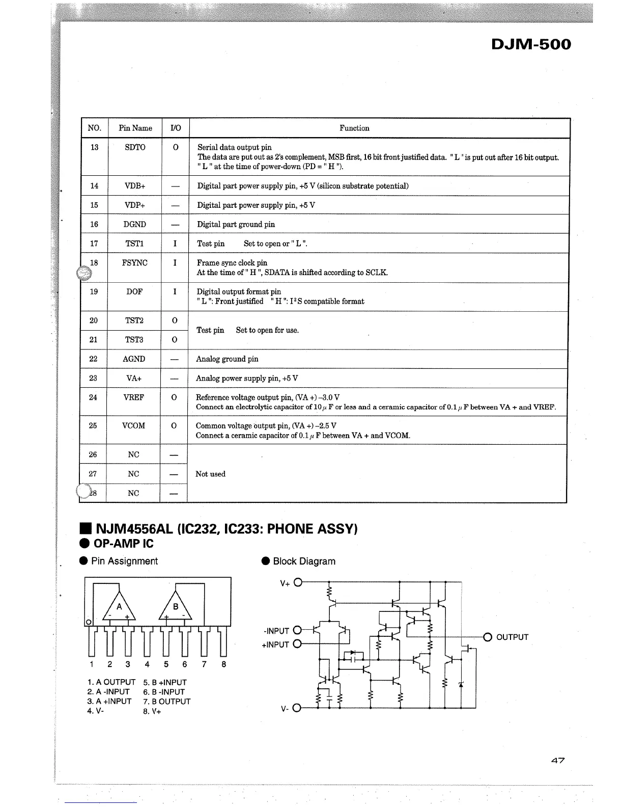
13 SDTO 0 Serial data output pin
The data are put out as 2's complement, MSB first, 16 bit front
justied data, "L" is put out afr 16 bit output,
" L " at the time of power-down (PD = " H ").
14
VDB+
-
Digital par power supply pin, +5 V (silcon substrate potential)
15
VDP+
-
Digital par power supply pin, +5 V
16 DGND
-
Digital par ground pin
17 TSTI I Test pin Set to open or " L ",
(~8
FSYNC I Frame sync clock pin
At the time of" H ", SDATA is shiftd according to SCLK.
19
DOF I Digital output format pin
"L ": Front justified " H ": 12 S compatible format
20 TST2
0
Test pin Set to open for use,
21
TST3 0
22 AGND
-
Analog ground pin
23
VA+
-
Analog power supply pin, +5 V
24 VREF 0 Reference voltage output pin, (VA +) -3,0 V
Connect an electrolytic capacitor ofl0,u F or less and a ceramic capacitor ofO,I,u F between VA + and VREF,
25 VCOM
0 Common voltage
output pin, (VA +) -2,5 V
Connect a ceramic capacitor of O,1,u F between VA + and VCOM,
26
NC
-
27 NC
-
Not used
(t~l8
NC
-
. NJM4556AL (lC232, IC233: PHONE ASSY)
.OP-AMPIC
. Pin Assignment
. Block Diagram
v+
OUTPUT
-INPUT
+INPUT
2345678
1,AOUTPUT
2. A -INPUT
3, A +INPUT
4, v-
5, B +INPUT
6, B -INPUT
7, B OUTPUT
8, v+
v-
47