


D
Donald ParkSep 4, 2025
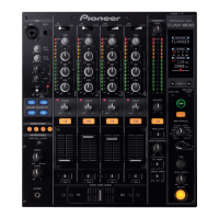
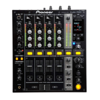
Why is there little or no sound coming from my Pioneer Music Mixer?
- AAdam SparksSep 4, 2025
If you experience little to no sound from your Pioneer Music Mixer, there are several potential causes. First, ensure the Input selector switch is set to the correct device that is currently playing. If you have an analog turntable connected, verify that the rear panel’s PHONO/LINE selector switch is set to [PHONO]. Check that all connection cables are properly connected and not disconnected. Also, make sure the terminals or plugs are clean; if dirty, clean and reconnect them. Finally, check the TRANSFORM lever and return it to its upright position if it has been tripped.