ORDER NO.
PIONEER CORPORATION 4-1, Meguro 1-chome, Meguro-ku, Tokyo 153-8654, Japan
PIONEER ELECTRONICS (USA) INC. P.O. Box 1760, Long Beach, CA 90801-1760, U.S.A.
PIONEER EUROPE NV Haven 1087, Keetberglaan 1, 9120 Melsele, Belgium
PIONEER ELECTRONICS ASIACENTRE PTE. LTD. 253 Alexandra Road, #04-01, Singapore 159936
PIONEER CORPORATION 2003
PHONO 1
/LINE 1
+
9
+
12-12
+
6-26
+
12-12
TRIM
HI
LOW
MIC SEND
SESSION IN
FADER START
TRANSFORM
MASTER LEVEL
REVERSE
CH-1 CH-2
CH-1 CH-2
REVERSE
FEELING
ADJ.
LR
REVERSE
TRANSFORM
FADER START
FOOT SW POWER
PHONES
CH-1 SEND CH-2 SEND
HI
+
6-26
MID
+
6
MAXMIN
10
9
14
9
5
3
1
0
1
–
–
–
–
–
–
–
–
–
–
–
–
3
6
9
15
22
dB dB
14
9
5
3
1
0
1
3
6
9
15
22
8
7
6
5
4
3
2
1
0
10
9
8
7
6
5
4
3
2
1
0
-26
LOW
TAP TAP
TIME/SELECT
MIX/DEPTH
EFFECT EFFECT
MAXMIN
TIME/SELECT
MIX/DEPTH
EQ
CD 1
BANK 3
FX ADJ. FX ADJ.
BANK
EDIT
BANK
EDIT
FADER
CURVE
FADER
CURVE
–
PHONO 2
/LINE 2
+
9
+
6-26
TRIM
HI
+
6-26
MID
+
6-26
LOW
EQ
CD 2
–
0
–
BOOTH/SESSION OUT
0
–
PHONES
SELECT
CH-1 CH-2
0
–
0
–
0
–
OFF
ON
LOCK ON
21
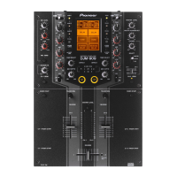
PROFESSIONAL 2CHANNEL MIXER
DJM-909
MIC LEVEL
CH-1 FADER START
C.F.1 FADER START
CH-2 FADER START
C.F.2 FADER START
OFF OFF
ON
ON
MASTER LEVEL
EFFECT
CUE
MASTER
CH-1MIC
BANK 2
BANK 1 BANK 1
BANK 2
BANK 3
DJM-909
RRV2871
DJ MIXER
DJM-909
THIS MANUAL IS APPLICABLE TO THE FOLLOWING MODEL(S) AND TYPE(S).
Model Type Power Requirement Remarks
DJM-909 KUCXJ AC120V
DJM-909 WYXJ AC220 - 240V
DJM-909 TLTXJ AC110 - 240V
For details, refer to "Important symbols for good services" .
T-ZZY DEC. 2003 printed in Japan