EasyManua.ls Logo

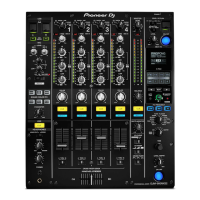
Pioneer DJM-900NXS2 Service Manual

Pioneer DJM-900NXS2
71 pages
To Next Page IconTo Next Page
Page #1 background imageLoading...
Page #1 background image
ORDER NO.
PIONEER CORPORATION
1-1, Shin-ogura, Saiwai-ku, Kawasaki-shi, Kanagawa 212-0031, Japan
PIONEER ELECTRONICS (USA) INC. P.O. Box 1760, Long Beach, CA 90801-1760, U.S.A.
PIONEER EUROPE NV Haven 1087, Keetberglaan 1, 9120 Melsele, Belgium
PIONEER ELECTRONICS ASIACENTRE PTE. LTD. 2 Jalan Kilang Barat, #07-01, Singapore 159346
Pioneer DJ Corporation 2016
2016 Printed in Japan
DJM-900NXS2
RRV4643
DJ MIXER
DJM-900NXS2
THIS MANUAL IS APPLICABLE TO THE FOLLOWING MODEL(S) AND TYPE(S).
THIS SERVICE MANUAL SHOULD BE USED TOGETHER WITH THE FOLLOWING MANUAL(S).
Model Type Power Requirement Remarks
DJM-900NXS2 LSYXJ AC 110 V to 240 V
DJM-900NXS2 UXJCB AC 110 V to 240 V
DJM-900NXS2 XJCN AC 220 V
Model Order No. Remarks
DJM-900NXS2 RRV4644 SCHEMATIC DIAGRAM, PCB CONNECTION DIAGRAM, PCB PARTS LIST
K-MZV FEB.

Other manuals for Pioneer DJM-900NXS2

Question and Answer IconNeed help?

Do you have a question about the Pioneer DJM-900NXS2 and is the answer not in the manual?

Pioneer DJM-900NXS2 Specifications

General IconGeneral
MIDI outYes
Phono inputs (RCA)4
USB 2.0 ports quantity3
Digital audio coaxial out1
Sample rate96 kHz
Frequency range20 - 40000 Hz
Channels quantity4 channels
Line Signal-to-Noise Ratio (SNR)105 dB
Total Harmonic Distortion (THD)0.005 %
Power consumption (typical)42 W
TypeMagvel Fader
Weight and Dimensions IconWeight and Dimensions
Depth414.2 mm
Width333 mm
Height107.9 mm
Weight8000 g

Summary

SAFETY INFORMATION

SERVICE PRECAUTIONS

SPECIFICATIONS

BLOCK DIAGRAM

DIAGNOSIS

POWER ON SEQUENCE

Step-by-step process of the unit's power-on sequence for diagnostic checks.

TROUBLESHOOTING

Lists common issues, their causes, and corrective actions for troubleshooting.

INFORMATION ON POWER DIAGNOSTICS

Explains the power monitoring circuit and diagnostic procedures for voltage errors.

ERROR INDICATIONS

Categorizes error codes for normal startup and firmware updates.

CONNECTION CHECK WITH EACH INTERFACE

Verifies USB, LAN, and other interface communication.

SERVICE MODE

TEST MODE

Details various diagnostic and calibration modes including version check, fader/VR tests, and device confirmation.

DISASSEMBLY

CONTROL PANEL SECTION

Step-by-step instructions for removing and disassembling the control panel.

SETTING AND ADJUSTMENT

UPDATING OF THE FIRMWARE

Instructions for downloading, preparing, and performing firmware updates.

Related product manuals