EasyManua.ls Logo

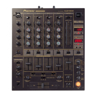
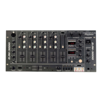
Pioneer DJM-500 Service Manual

Pioneer DJM-500
43 pages
To Next Page IconTo Next Page
Page #1 background imageLoading...
Page #1 background image
(I PIONEER~
Th Art of Entertinment
Serviee
Manual
ilIJ'JltlWi.
'l'~~"'" QiilW\§l\' ~~~'
&æ "" '00 ø llÎ
o Cl Q
ORDER NO.
RRV1405
OJ MIXER
.J
-500
THIS MANUAL IS APPLICABLE TO THE FOLLOWING MODEL(S) AND TYPE(S).
Model
Type
Power Requirement
The voltage can be converted by the following method.
DJM.500
KUC
0
AC120V
RELM
0
ACll0-120V/220-240V
With the voltage selector
Cr -+
CONTENTS
1. SAFETY INFORMATION ........................... 2
2. EXPLODED VIEWS, PACKING AND
PARTS LIST ............................................. 3
3. BLOCK DIAGRAM.................................... 7
4. SCHEMATIC AND PCB CONNECTION
DIAGRAMS ............................................. 10
r~
5. PCB PARTS LIST .................................... 41
6. IC INFORMATION .................................... 46
7. DISASSEMBLY .......................................53
8. PANEL FACILITIES .......................... ....... 55
9. SPECIFICATIONS .................................... 59
PIONEER ELECTRONIC CORPORATION 4-1, Maguro 1-Chome, Meguro-ku, Tokyo 153, Japan
PIONEER ELECTRONICS SERVICE INC. P,O, Box 1760, Long Beach, CA 90801-1760, U,S,A,
PIONEER ELECTRONIC (EUROPEl N.V. Haven 1087 Keetberglaan 1, 9120 Melsele, Belgium
PIONEER ELECTRONICS ASIACENTRE PTE. LTD. 501 Orchard Road, #10-00 Lane Crawford Place, Singapore 0923
(§ PIONEER ELECTRONIC CORPORATION 1995 T-DFY NOV, 1995 Printed in Japan

Other manuals for Pioneer DJM-500

Questions and Answers:

Pioneer DJM-500 Specifications

Power IconPower
power supply voltageAC 120 V, 60 Hz
power consumption41 W
Operating Environment IconOperating Environment
operating temperature+5 °C to +35 °C
operating humidity5 % to 85 %
Weight and Dimensions IconWeight and Dimensions
weight5.9 kg
external dimensions320 (W) x 357.4 (D) x 107 (H) mm

Summary

Safety Information

Safety Precautions

Precautions for customer and service technician safety, including leakage current checks.

Product Safety Notice

Safety related characteristics of parts and their importance for preventing hazards.

Exploded Views, Packing & Parts List

Packing Details

Details of packing materials and components for the DJM-500.

Exterior Parts List

List of exterior components and their part numbers.

Block Diagram Overview

Channel, Mixing & Master Sections

Explains input channels, assignment, mixing, and master output stages.

Monitor, Mic & Effects Sections

Details monitoring, mic input, and DSP effects processing.

BPM, CD Control & Operation

Covers BPM detection, CD player control, and system operation.

Schematics & PCB Diagrams

Waveform Observation Conditions

Specifies knob positions for waveform observation using an oscilloscope.

VR, Fader, Phone & Mic Jack Schematics

DSP & Effect VR Assy Schematics

Phone & Bal. Out Assy Schematics

Power Supply Related Schematics

Meter & 7Seg Assy Schematics

PCB Parts List

PCB Assemblies List

Lists major PCB assemblies and their part numbers.

Semiconductors, Resistors & Components

Parts list for semiconductors, switches, relays, and resistors.

IC Information and Pinouts

DSP & Analog Switch IC Details

Information on DSP, A/D converter, micro-computer, and analog switch array ICs.

Phone & VR Assy IC Details

Details on Op-Amp and analog switch ICs for Phone and VR assemblies.

Disassembly Procedures

Cross-Fader, Control Panel & EQ Disassembly

Steps for removing cross-fader, control panel, and equalizer units.

Shield Plate & Fader VR Assy Removal

Instructions for removing shield plate and Fader VR assembly.

Effect VR, Terminal & Phone Assy Removal

Procedures for removing Effect VR, Terminal, and Phone assemblies.

Panel Facilities Overview

Rear Panel Facilities (1-14)

Description of rear panel input/output terminals and controls.

Front Panel Facilities (1-24)

Overview of front panel layout and controls.

Front Panel Controls & Functions

Microphone & Channel Controls Details

Explains mic level, channel input, trim, EQ, and peak meters.

Master, BPM & Effect Controls Details

Details master level, BPM display, effector parameters, and monitor selection.

Fader, Crossfader & Monitor Controls Details

Covers channel faders, crossfader, monitor level, and EQ.

Effect Selection & Parameter Details

Details effector selection, parameter adjustment, and effect on/off.

Specifications (KUC Type)

Audio Section Specs

Input/output levels, frequency characteristics, SN ratio, and EQ specs.

Electrical & Other Specs

Power supply, dimensions, weight, and operating conditions.

Related product manuals