DJM-500
. AUTO BMP COUNTER SELECTOR
SECTION
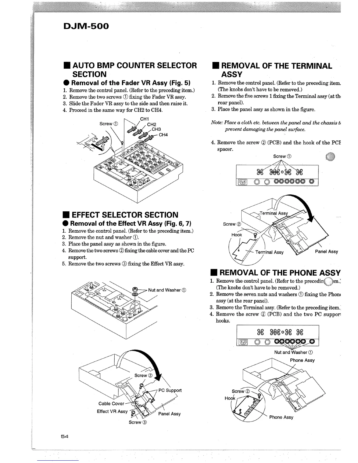
. Removal of the Fader VR Assy (Fig. 5)
1. Remove the control paneL. (Refer to the preceding item,)
2. Remove the two screws Q) fixing the Fader VR assy,
3. Slide the Fader VR assy to the side and then raise it.
4. ,Proceed in the same way for CH2 to CH4,
CHi
CH2
itti~CH3
',~CH4
. EFFECT SELECTOR SECTION
. Removal of the Effect VR Assy (Fig. 6, 7)
1. Remove the control paneL. (Refer to the preceding item.)
2, Remove the nut and washer Q),
3, Place the panel assy as shown in the figue,
4, Remove the two screws (% fig the cable cover and the PC
support.
5, Remove the two screws Q) fig the Effect VR assy,
Screw Q)
54
. REMOVAL OF THE TERMINAL
ASSV
1. Remove the control paneL. (Refer to the preceding
item,
(The knobs don't have to be removed,)
2. Remove the five screws 1 fing the Termal assy (at th
rear panel).
3. Place the panel assy as shown in the figue,
Note: Place a cloth etc, between the panel and the chassis t,
prevent damaging the panel surface.
4. Remove the screw (% (PCB) and the hook of the PCI
spacer,
Screw CD
~
I~I Ö ~ OOOOOO-lQ
. REMOVAL OF THE PHONE ASSV
1. Remove the control paneL. (Refer to the precedin(""'\m,;
(The knobs don't have to be removed,)
2, Remove the seven nuts and washers Q) fing the Phoni
assy (at the rear panel).
3. Remove the Terminal assy, (Refer to the preceding item.
4, Remove the screw (% (PCB) and the two PC suppori
hooks.
i~i
8€ OO 0 g. g.
Ö Ö
r)~~
Nut and Washer CD
Phone Assy