EasyManua.ls Logo

Pioneer HTV-2 - User Manual

Pioneer HTV-2
62 pages
Print Icon
To Next Page IconTo Next Page
Loading...
ORDER NO.
PIONEER ELECTRONIC CORPORATION 4-1, Meguro 1-Chome, Meguro-ku, Tokyo 153-8654, Japan
PIONEER ELECTRONICS SERVICE, INC. P.O. Box 1760, Long Beach, CA 90801-1760, U.S.A.
PIONEER ELECTRONIC (EUROPE) N.V. Haven 1087, Keetberglaan 1, 9120 Melsele, Belgium
PIONEER ELECTRONICS ASIACENTRE PTE. LTD. 501 Orchard Road, #10-00 Wheelock Place, Singapore 238880
PIONEER ELECTRONIC CORPORATION 1998
RRV1977
HOME THEATER SYSTEM
HTV-2
T – ZZE JUNE 1998 Printed in Japan
Remarks
KUXC type
Service
Manual
Component
POWERED SUBWOOFER
HTV-SW2/KUCXC
HTV-2
KCXC type
CONTROL CENTER
AMPLIFIER
HTV-SW2/KUCXC
HTV-A2/KUCXJ HTV-A2/KUCXJ
HTV-C2/AUXJ HTV-C2/ACXJ
RRV1978
RRV1970
RRV1979
Model
The HTV-2 is a combination of the components in the Table below.
For details regarding each component, refer to the Service Manuals below.
Question and Answer IconNeed help?

Do you have a question about the Pioneer HTV-2 and is the answer not in the manual?

Overview

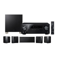
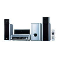
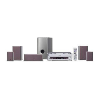
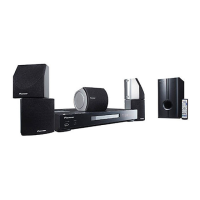
This document serves as a service manual for the Pioneer Home Theater System HTV-2, a combination of several components designed to work together. The HTV-2 system consists of a Control Center (HTV-C2), a Powered Subwoofer (HTV-SW2), and an Amplifier (HTV-A2). Each component has its own dedicated service manual for detailed information, with the HTV-2 manual (RRV1977) providing an overview of the system's composition and general instructions.

Function Description:

The HTV-2 is a home theater system designed to provide an immersive audio experience. The Control Center (HTV-C2) acts as the central hub, managing input selection, sound processing, and user interface. It receives audio signals and processes them for distribution to the amplifier and subwoofer. The Powered Subwoofer (HTV-SW2) is responsible for reproducing low-frequency sounds, adding depth and impact to the audio. The Amplifier (HTV-A2) boosts the audio signals from the Control Center to drive the main speakers (Front L/R channels) and the subwoofer. The system supports Dolby Virtual surround sound, enhancing the spatial audio experience.

Important Technical Specifications:

Control Center (HTV-C2):

  • Power Requirement: AC26V, supplied from another system component (specifically, the Amplifier HTV-A2/KUCXJ).
  • Input (Sensitivity/Impedance): INPUT 1, 2: 200 mV/22 kΩ.
  • Speaker Section (Front L/R): 8.7 cm cone type.
  • Dimensions: 610 (W) x 110 (H) x 166 (D) mm (24-3/16 (W) x 4-5/16 (H) x 6-9/16 (D) in).
  • Weight (without package): 3.8 kg (8 lb 6 oz).
  • Display: FL Tube (AAV7052) with pattern area for various indicators.
  • IC Components: Features a Dolby Virtual Decoder (CXD2724Q) for sound processing and a System Control Micro Computer (PDG221A) for overall system management.
  • Connectors: Includes various connectors for input/output, power, and communication with other system components, such as CN5001 (XKP3019-A) for display, CN3001 (HLEM195-1) for main board, CN503 (KP250NA4) and CN203 (KM250NA4L) for speaker output, and JA4001 (VKN1070) for amplifier connection.

Powered Subwoofer (HTV-SW2):

  • Speaker Section (Subwoofer): 20 cm cone type.
  • Power Requirement: AC120V, 60 Hz.
  • Power Consumption: 150 W.
  • Dimensions: 364 (W) x 360 (H) x 371 (D) mm (14-5/16 (W) x 14-3/16 (H) x 14-5/8 (D) in).
  • Weight (without package): 13.5 kg (29 lb 12 oz).
  • Amplifier Section (Subwoofer channel): Continuous average power output of 60 watts* per channel, min., at 8 ohms, from 40 Hz to 180 Hz with no more than 1%** total harmonic distortion. (*Measured pursuant to the Federal Trade Commission's Trade Regulation rule on Power Output Claims for Amplifiers. **Measured by Audio Spectrum Analyzer.)

Amplifier (HTV-A2):

  • Power Requirement: AC120V.
  • Amplifier Section (Front left and right channels): Continuous average power output of 30 watts* per channel, min., at 8 ohms, from 180 Hz to 15,000 Hz with no more than 1%** total harmonic distortion. (*Measured pursuant to the Federal Trade Commission's Trade Regulation rule on Power Output Claims for Amplifiers. **Measured by Audio Spectrum Analyzer.)
  • IC Components: Utilizes STK407-050B for the power amplifier section (PAMP Assy) and various NJM4558MD operational amplifiers for audio processing.

Usage Features:

  • System Integration: The HTV-2 is designed as a cohesive system. The Control Center, Powered Subwoofer, and Amplifier are intended to be connected and operated together. The Control Center does not operate normally by itself and requires connection to the Amplifier HTV-A2/KUCXJ for adjustment and operation inspection.
  • Remote Control: The system includes a remote control unit (AZN7713) for convenient operation, allowing users to select input sources, adjust volume, change sound modes (e.g., Surround Mode, Dolby Virtual), and control other brand devices.
  • Auto Standby Function: The unit features an auto standby function that automatically turns the power ON/OFF based on the presence or absence of an input signal. If no input signal is detected for 5 minutes, the system will enter standby. If an input signal is received while in standby, the power will automatically turn ON.
  • Display Options: The DISPLAY button allows users to cycle through various settings and switch to Dimmer Mode to adjust display brightness.
  • Sound Control: Dedicated buttons for SOUND (BASS/TREBLE/BALANCE/S.W. LEVEL/EFFECT) and SURROUND MODE enable users to customize their audio experience.
  • Input Selection: The INPUT button allows users to select between different input devices (INPUT 1, 2).

Maintenance Features:

  • Service Manuals: Comprehensive service manuals are provided for the overall HTV-2 system (RRV1977) and its individual components: HTV-C2 (RRV1978), HTV-SW2 (RRV1970), and HTV-A2 (RRV1979). These manuals contain detailed information for qualified service technicians.
  • Parts List: Each manual includes an exploded view and a parts list, identifying components by mark number, description, and part number. Parts marked "NSP" are generally unavailable.
  • Safety Precautions: The manuals emphasize safety information, including warnings about lead in solder and the importance of using identical replacement parts for components marked with a triangle (▲) to maintain safety characteristics. Leakage current checks are outlined for USA models.
  • Test Mode: The Control Center (HTV-C1/C2) features a test mode for diagnostic purposes. This mode can be entered via a remote control command or by short-circuiting specific points on the DISPLAY Assy. The test mode allows for DSP checks, FL segment checks, and verification of the auto standby function.
  • Diagnosis Methods: Specific diagnosis methods are provided for the Power Amplifier section (PAMP Assy) and the AFPS Assy in the Amplifier (HTV-A1/A2) manual, detailing steps for disassembly, short-circuiting test terminals, and signal analysis.
  • Component-Specific Instructions: Disassembly and reassembly instructions are provided for components like the woofer and amplifier in the HTV-SW2 manual, highlighting the number of screws and terminal orientation.
  • PCB Diagrams: PCB connection diagrams are included, showing part numbers, symbols, and views of the printed circuit boards to aid in troubleshooting and repair.
  • Waveforms: Waveform diagrams are provided for various test points in the Control Center and Amplifier sections, showing expected voltage levels and signal characteristics to assist in diagnosis.
  • IC Pin Functions and Voltages: Detailed tables list pin names, I/O types, descriptions, and expected voltage levels for key integrated circuits (ICs) under different operating conditions, which are crucial for component-level troubleshooting.

Pioneer HTV-2 Specifications

General IconGeneral
BrandPioneer
ModelHTV-2
CategoryHome Theater System
LanguageEnglish

Related product manuals