Do you have a question about the Pioneer PD-M701 and is the answer not in the manual?
Essential precautions for service technicians and customer safety.
Special safety characteristics of parts and replacement guidelines.
Information on laser radiation hazards, warnings, and characteristics.
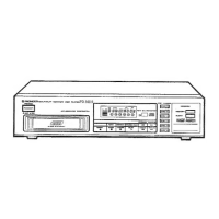
Detailed breakdown of external components and their part numbers.
Comprehensive list of all parts with their respective part numbers.
List of parts required for product packing.
Detailed circuit diagrams for the device's electronic components.
Visual representations of signal waveforms at various test points.
Diagrams illustrating the functional blocks of integrated circuits.
Details on the function of each pin for key integrated circuits.
Visual representation of how different PC boards are interconnected.
Categorized list of major assembled circuit boards.
List of semiconductor components with their part numbers.
List of capacitor components with their part numbers.
List of resistor components and their values.
List of switch components and their types.
Miscellaneous parts not fitting other categories.
Procedures for calibrating the player's mechanical and electronic systems.
Step-by-step guide for performing necessary adjustments.
Key for understanding abbreviations used in adjustment procedures.
Locations of test points and adjustable resistors for calibration.
Instructions for entering and using the service test mode.
Explanation of key functions when operating in test mode.
Control of pickup movement within the disc during test mode.
Functions for stopping operations and ejecting the disc magazine.
Sequence of operations for playing a disc using test mode.
Procedure to verify and adjust the focus servo offset.
Procedure to verify tracking photo diode sensitivity balance.
Adjusting pickup tilt for optimal RF signal readouts.
Procedure to verify the playback RF signal amplitude.
Procedure to optimize the focus servo loop gain.
Procedure to optimize the tracking servo loop gain.
Important notes regarding parts for different model types.
Comparison of parts differing between PD-M701/KU and other models.
Specifics for the Mother Board Assembly (PWM1589).
Information on the Headphone Board Assembly for various models.
Instructions for connecting audio and control cords.
Details on using the CD-Deck synchro function with a cassette deck.
Guidance on correctly connecting the power cord for sound quality.
Connecting for integrated remote control operation with an amplifier.
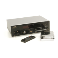
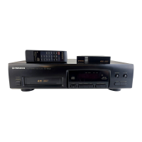
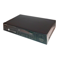
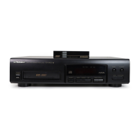
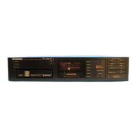
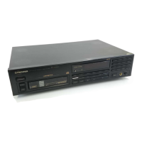
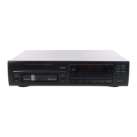
Identification and function of front panel controls and indicators.
Guidelines for operating the remote control unit effectively.
Overview of the player's physical and power specifications.
Technical details on the audio performance and characteristics.
Information on audio line output and headphone jack specifications.
List of operational features and playback modes.
List of included accessories and their quantity.
| power requirements (European models) | AC 220 - 230 V, 50/60 Hz |
|---|---|
| power requirements (U.K., Australian models) | AC 230 - 240 V, 50/60 Hz |
| power requirements (U.S., Canadian models) | AC 120 V, 60 Hz |
| power requirements (Other models) | AC 110/120 - 127/220/240V (switchable) 50/60 Hz |
| power consumption (U.S., Canadian models) | 12W |
| operating temperature | +41°F - +95°F |
|---|
| frequency response | 2 Hz - 20 kHz |
|---|---|
| signal-to-noise ratio | 102 dB or more (EIAJ) |
| dynamic range | 96 dB or more (EIAJ) |
| harmonic distortion | 0.003 % or less (EIAJ) |
| output voltage | 2.0V |
| wow and flutter | less than ±0.001 % (W.PEAK) (below measurable level) (EIAJ) |
| channel separation | 2-channel (stereo) |
| weight | 4.0 kg |
|---|---|
| external dimensions | 420(W) X 295(D) X 130(H) mm |
| external dimensions (inches) | 16-9/16(W) X11-10/16(D) X 5-2/16(H) in |