PDP-425CMX
128
1234
1234
C
D
F
A
B
E
7.1.3 TROUBLESHOOTING
Circuit No.
Connector
Name
MAIN_PWB KEY_PWB COMM_SLOT_IF SENB_PWB SENC_PWB SEND_PWB LED_PWB AUDIO_PWB
CN9011 CN2201
−−−−−−
SW
CN9010
−
CN2302
−−−−−
−
CN9501
−− −−−−−
TM
−− −
CN1001
−−−−
TM1
−− − −
CN1101
−−−
TM2
−− − − −
CN1201
−−
TM3
−−CN2301 −−−
CN2401
−
−
CN9008
−− −−−−−
PV
CN9003
−− −−−−−
FA
CN9004
−− −−−−−
FB
CN9006
−− −−−−−
PM
CN9007
−− −−−−−
PN1
CN9012
−− −−−−−
PN2
CN8501
−− −−−−−
AD1
CN8502
−− −−−−−
AD2
CN9001
−− −−−−
CN3004 AU
• In a case of a power-supply-related abnormality, such as no power and LEDs' flashing or lighting as an alarm indication:
Proceed to "1. Abnormality in power supply" (P138).
• In a case of an image-related abnormality, such as no image on the screen:
Proceed to "2. Abnormality in images" (P140).
• In a case of no video loop output (in a model for industrial use):
This is caused by a failure in the MAIN PWB.
• In a case of an audio-related abnormality, such as no sound:
Proceed to "3. Abnormality in audio" (P148).
• In a case when a remote control unit does not function:
Proceed to "4. Failure of a remote control unit" (P152).
Note:
• If symptoms persist after replacement of parts, such as ICs, following the diagnosis results of this failure-analysis chart, it is
recommended to replace the whole PC board, as short-circuiting or breaking of printed wiring of board patterns is suspected.
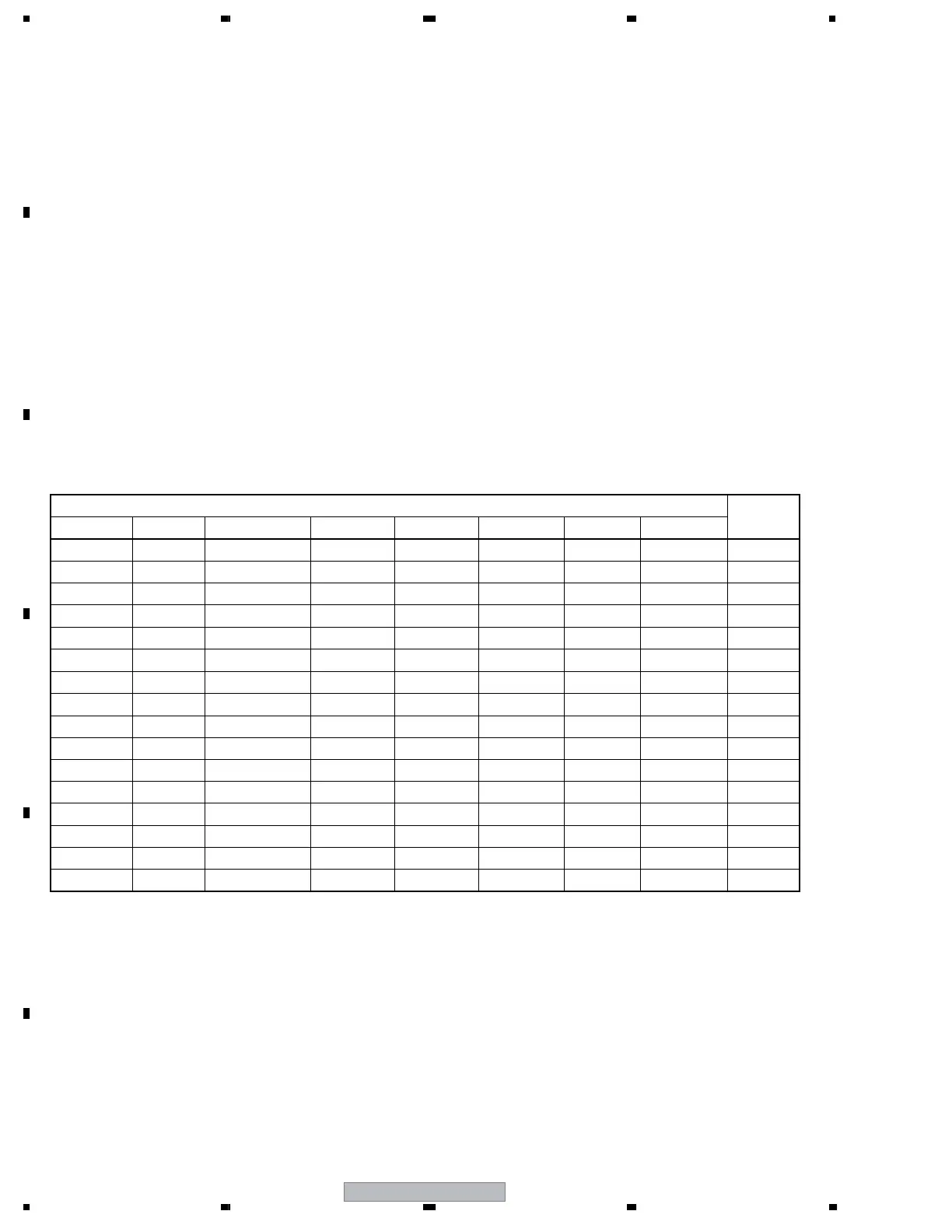
• In this failure-analysis chart, a connector is expressed either by its circuit number (CN****) or by its name.
The correspondence of a circuit number to a connector name is shown in the table below:
(E.g.: SW connector on the MAIN_PWB is CN9011)
* When the Power-down is occured as the key-lock is effective.
• Please pull out the AC-plug, and make the state to stand-by mode.
• The lock is cancelled when the key-lock button is pressed for 5 seconds.
 Loading...