PDP-502MX, PDP-502MXE
4
7 Charged Section
The places where the commercial AC power is used without
passing through the power supply transformer.
If the places are touched, there is a risk of electric shock. In addition,
the measuring equipment can be damaged if it is connected to the
GND of the charged section and the GND of the non-charged
section while connecting the set directly to the commercial AC
power supply. Therefore, be sure to connect the set via an insulated
transformer and supply the current.
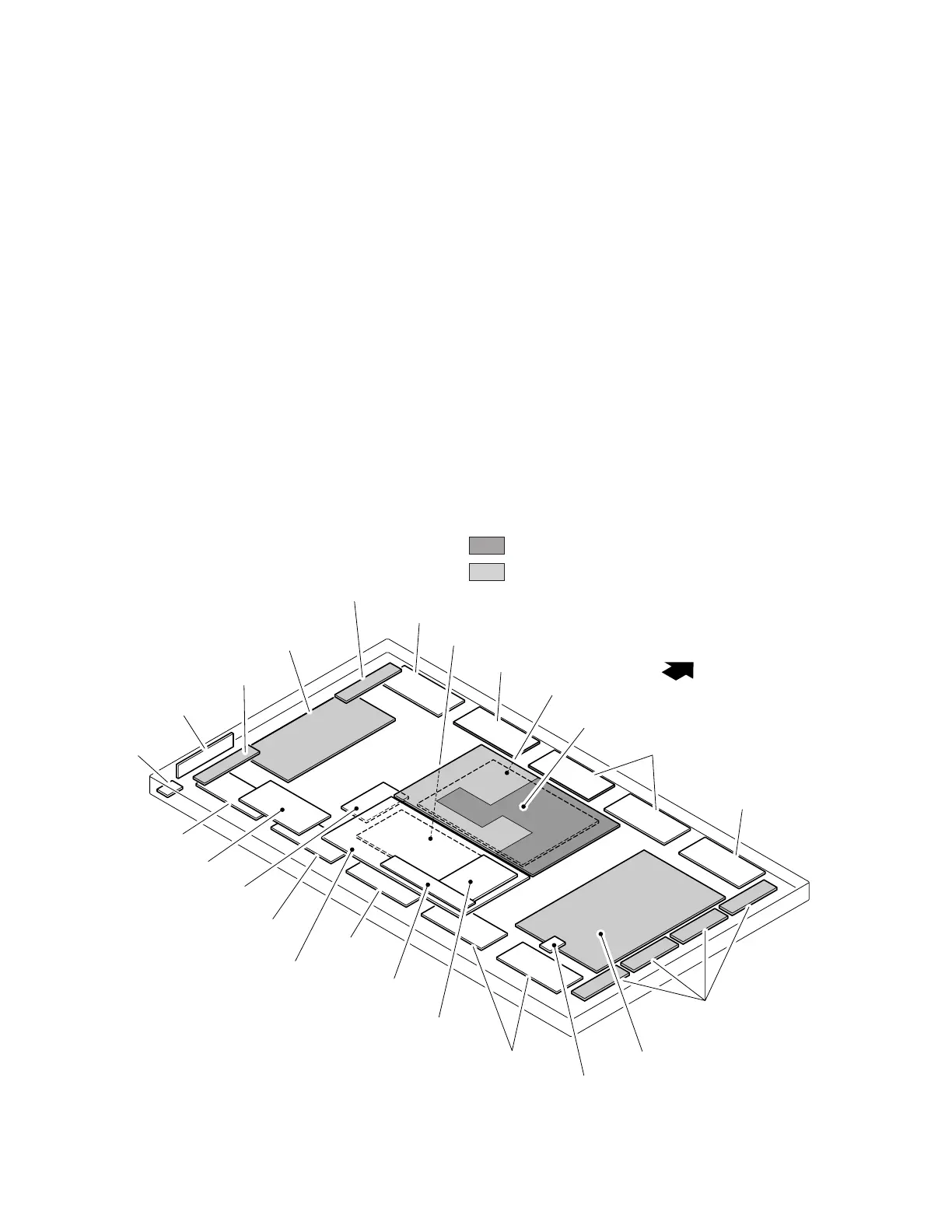
1.3 CHARGED SECTION AND HIGH VOLTAGE GENERATING POINT
7 Charged Section
(Power supply primary side)
1. AC Power Cord
2. AC Inlet with Filter
3. Power Switch (S1)
4. Fuse (In the MAIN POWER ASSY)
5. STB Transformer and Converter Transformer
(In the MAIN POWER ASSY)
6. Other primary side of the MAIN POWER ASSY
7 High Voltage Generating Point
The places where voltage is 100V or more except for the charged
places described above. If the places are touched, there is a risk of
electric shock.
1. POWER SUPPLY MODULE (170V)
2. X DRIVE ASSY (170V)
3. Y DRIVE ASSY (–200V to 250V)
6. SCAN MODULE (250V)
For the places, refer to the EXPLODED VIEWS, the SCHEMATIC
DIAGRAM and the PCB CONNECTION DIAGRAM sections.
Part is the high voltage generating points other than the
charged section.
Part is charged section.
INPUT ASSY
VIDEO ASSY
AUDIO ASSY
CONTROL ASSY
DIGITAL VIDEO ASSY
X CABLE U ASSY
X CABLE D ASSY
SIDE SWITCH ASSY
IR RECEIVER ASSY
SCAN MODULE
CABLE ASSY
CABLE ASSY
CABLE ASSY
CABLE ASSY
CABLE ASSY
SP TERMINAL ASSY
CABLE ASSY
CABLE ASSY
CABLE ASSY
UCOM ASSY
YC SEPA. ASSY
MAIN POWER ASSY
TOP
X DRIVE ASSY
Y DRIVE ASSY
 Loading...