PDP-505PE
4
1234
1234
C
D
F
A
B
E
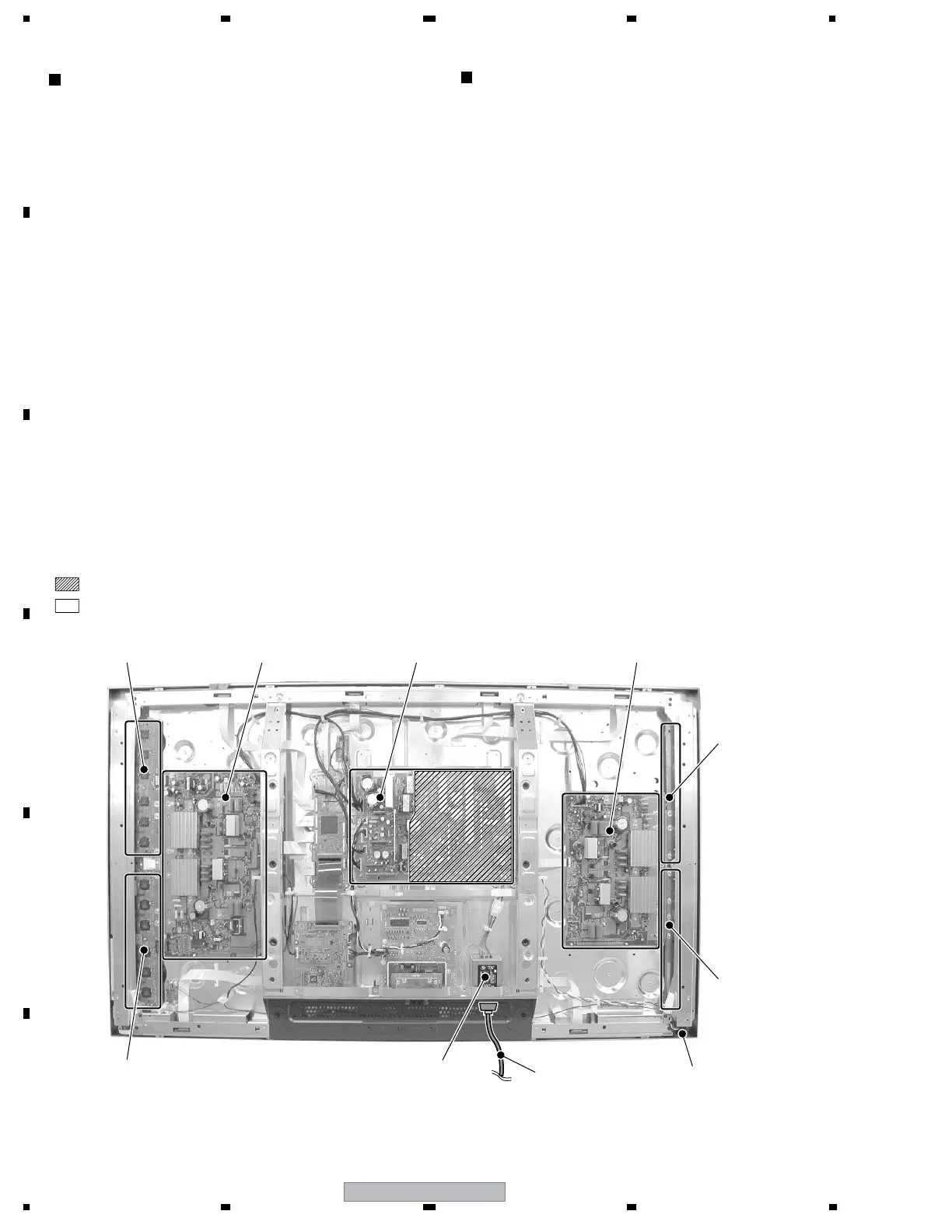
Fig.1 Charged Section and High Voltage Generating Point (Rear View)
Charged Section
The places where the commercial AC power is used without
passing through the power supply transformer.
If the places are touched, there is a risk of electric shock. In
addition, the measuring equipment can be damaged if it is
connected to the GND of the charged section and the GND of the
non-charged section while connecting the set directly to the
commercial AC power supply. Therefore, be sure to connect the
set via an insulated transformer and supply the current.
1. AC Power Cord
2. AC Inlet with Filter
3. Power Switch (S1)
4. Fuse (In the POWER SUPPLY Unit)
5. STB Transformer and Converter Transformer
(In the POWER SUPPLY Unit)
6. Other primary side of the POWER SUPPLY Unit
High Voltage Generating Point
The places where voltage is 100V or more except for the charged
places described above. If the places are touched, there is a risk of
electric shock.
1. POWER SUPPLY Unit................................................... (223V)
2. 50 X DRIVE Assy .......................................... (–230V to 223V)
3. 50 Y DRIVE Assy .......................................................... (353V)
4. 50 SCAN A Assy ............................................................ (353V)
5. 50 SCAN B Assy ............................................................ (353V)
6. X CONNECTOR AAssy ................................ (–230V to 223V)
7. X CONNECTOR B Assy ............................... (–230V to 223V)
: Part is the High Voltage Generating Points
other than the Charged Section.
: Part is Charged Section.
AC Inlet with Filter
Power Cord Power Switch
(S1)
Discharge the VSUS voltage, as shown below:
[Method for discharging the VSUS voltage]
1. Set DRF_SW on the DIGITAL VIDEO Assy to ON (Drive
OFF status). *1, 2
2. Leave the switch at that position for about 20-30 seconds.
3. If the power is on, turn it off. Then return DRF_SW to the OFF
position. *3
Notes
*1: You can also set the unit to "Drive OFF status" by sending the
"DRF" RS232C command from the PC.
*2: DRF_SW can be switched whether the power is on or off.
*3: Power-down will occur if DRF_SW is set to OFF while the
power is on. (See "7.1.6 Power on/off function for the large-
signal system".)
POWER SUPPLY Unit50 Y DRIVE Assy50 SCAN B Assy
50 SCAN A Assy
50 X DRIVE Assy
X CONNECTOR
A Assy
X CONNECTOR
B Assy

 Loading...